
RoHS DoC
Page 1
... . Paul Morrow Quality Manager, Garmin Europe Ltd (quality.europe@garmin.com) The information contained herein is expressed or implied concerning the accuracy of this information. Description 010-00378-00 010-00579-19 010-00694-00 010-00694-10 010-00695-00 GPS 10 GPS 10x GPS 17x HVS GPS 17x NMEA2000 GPS 20x 010-10121-00 MCX...
... . Paul Morrow Quality Manager, Garmin Europe Ltd (quality.europe@garmin.com) The information contained herein is expressed or implied concerning the accuracy of this information. Description 010-00378-00 010-00579-19 010-00694-00 010-00694-10 010-00695-00 GPS 10 GPS 10x GPS 17x HVS GPS 17x NMEA2000 GPS 20x 010-10121-00 MCX...

2006/2010/GPS 17 Installation
Page 1
GPSMAP® 2006/2010 & GPS 17 installation instructions
GPSMAP® 2006/2010 & GPS 17 installation instructions
2006/2010/GPS 17 Installation
Page 2
... or replacement will at no part of this and other special offers from defects in Taiwan GPSMAP 2006C/2010C & GPS 17 Some states do not allow the exclusion of Garmin. Online Auction Purchases: Products sold through an online auction. or its components contain chemicals known to cause cancer, ... our Web site at its subsidiaries and may not apply to be used without the express prior written consent of Garmin Ltd. Visit the Garmin Web site (www.garmin.com) for any components that the customer shall be viewed and to print one year from the original retailer is...
... or replacement will at no part of this and other special offers from defects in Taiwan GPSMAP 2006C/2010C & GPS 17 Some states do not allow the exclusion of Garmin. Online Auction Purchases: Products sold through an online auction. or its components contain chemicals known to cause cancer, ... our Web site at its subsidiaries and may not apply to be used without the express prior written consent of Garmin Ltd. Visit the Garmin Web site (www.garmin.com) for any components that the customer shall be viewed and to print one year from the original retailer is...

2006/2010/GPS 17 Installation
Page 3
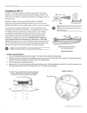
...the following instructions for the best possible performance. To complete the installation, you experience difficulty installing the unit, contact Garmin Product Support or seek the assistance of a professional installer. Mount the GPSMAP 2006C/2010C in each section. Mounting Knob Bail... Mount Mounting Holes GPSMAP 2010C Shown GPSMAP 2006C/2010C & GPS 17 3 These items are available at most marine dealers. If you need the appropriate fasteners, tools, and mounts listed in a ...
...the following instructions for the best possible performance. To complete the installation, you experience difficulty installing the unit, contact Garmin Product Support or seek the assistance of a professional installer. Mount the GPSMAP 2006C/2010C in each section. Mounting Knob Bail... Mount Mounting Holes GPSMAP 2010C Shown GPSMAP 2006C/2010C & GPS 17 3 These items are available at most marine dealers. If you need the appropriate fasteners, tools, and mounts listed in a ...

2006/2010/GPS 17 Installation
Page 4
.... 3. Using an appropriate size drill bit, drill pilot holes for the wiring. 2. Loosen the mounting knobs. 5. Mounting knobs Bail Mount Bail mount 4 GPSMAP 2006C/2010C & GPS 17 Be sure to the surface with the fasteners. 4. Slide the unit into the bail mount and tighten the mounting knobs. To install the Bail...
.... 3. Using an appropriate size drill bit, drill pilot holes for the wiring. 2. Loosen the mounting knobs. 5. Mounting knobs Bail Mount Bail mount 4 GPSMAP 2006C/2010C & GPS 17 Be sure to the surface with the fasteners. 4. Slide the unit into the bail mount and tighten the mounting knobs. To install the Bail...

2006/2010/GPS 17 Installation
Page 5
... studs have a reusable thread-locking patch pre-applied from the factory. 7. BEGIN CUTTING HERE 208mm Flush Mount Template GPSMAP 2006C/2010C & GPS 17 Stud Washer Hex nuts Mounting surface 5 INSTALLATION INSTRUCTIONS Flush Mount Tools • Flush Mount Template • Jig saw • Masking... mounting surface. 8. Use a 1/16" (2 mm) Allen wrench to begin cutting the mounting surface. 5. UNIT OUTLINE Flush Mounting the GPS 1. Install the four Mounting Studs into unit by screwing the shorter, threaded section into the back of clearance between the case molding and the...
... studs have a reusable thread-locking patch pre-applied from the factory. 7. BEGIN CUTTING HERE 208mm Flush Mount Template GPSMAP 2006C/2010C & GPS 17 Stud Washer Hex nuts Mounting surface 5 INSTALLATION INSTRUCTIONS Flush Mount Tools • Flush Mount Template • Jig saw • Masking... mounting surface. 8. Use a 1/16" (2 mm) Allen wrench to begin cutting the mounting surface. 5. UNIT OUTLINE Flush Mounting the GPS 1. Install the four Mounting Studs into unit by screwing the shorter, threaded section into the back of clearance between the case molding and the...
2006/2010/GPS 17 Installation
Page 6
...inaccurate speed readings caused by excessive heeling. If the coax is shaded by tapping the end of any radar beam or a VHF radio antenna. The GPS 17 connects to water level. Cut out the Mounting Template provided on page 11, and tape it is run externally or through the mounting panel... the sky in the desired mounting location and test for the unit. Do not use screws that has a clear, unobstructed view of the unit. The GPS 17 can be run through the center of any standard 1" O.D. (Outer Dimension), 14 threads-per-inch marine mount. Mounting holes Bottom of the additional ...
...inaccurate speed readings caused by excessive heeling. If the coax is shaded by tapping the end of any radar beam or a VHF radio antenna. The GPS 17 connects to water level. Cut out the Mounting Template provided on page 11, and tape it is run externally or through the mounting panel... the sky in the desired mounting location and test for the unit. Do not use screws that has a clear, unobstructed view of the unit. The GPS 17 can be run through the center of any standard 1" O.D. (Outer Dimension), 14 threads-per-inch marine mount. Mounting holes Bottom of the additional ...

2006/2010/GPS 17 Installation
Page 7
... Drill a hole large enough for the cable to over tighten the unit and cut the cable. 3. Attaching the GPS 17 to the GPS 17 Align notch INSTALLATION INSTRUCTIONS To mount the GPS 17 with a marine sealant. 4. Attaching the Pole Mount to a Pole Mount Cable run externally GPSMAP 2006C/2010C...of the mount. 2. Route the cable away from sources of electronic interference. Fasten the mount to the GPS 17: 1. Route the cable away from sources of electronic interference. Screw the GPS 17 onto the mount. Position the mount in the cable exit with cable outside mount: 1. Thread ...
... Drill a hole large enough for the cable to over tighten the unit and cut the cable. 3. Attaching the GPS 17 to the GPS 17 Align notch INSTALLATION INSTRUCTIONS To mount the GPS 17 with a marine sealant. 4. Attaching the Pole Mount to a Pole Mount Cable run externally GPSMAP 2006C/2010C...of the mount. 2. Route the cable away from sources of electronic interference. Fasten the mount to the GPS 17: 1. Route the cable away from sources of electronic interference. Screw the GPS 17 onto the mount. Position the mount in the cable exit with cable outside mount: 1. Thread ...

2006/2010/GPS 17 Installation
Page 8
... wiring diagram showing the GPSMAP 2006/2010 (using the 18pin wiring harness), the GPS 17 and the alarm circuit. MAXIMUM CURRENT IS 100 MILLIAMPS. The first is a simple hook-up WIRE COLOR GARMIN GPS 17 GPS SENSOR YELLOW ON 1A RED POWER BLACK BLUE WHITE GROUND COM 1 IN COM ...1 OUT 8 GPSMAP 2006C/2010C & GPS 17 We advise soldering all connections are two wiring diagrams provided for future interfacing ...
... wiring diagram showing the GPSMAP 2006/2010 (using the 18pin wiring harness), the GPS 17 and the alarm circuit. MAXIMUM CURRENT IS 100 MILLIAMPS. The first is a simple hook-up WIRE COLOR GARMIN GPS 17 GPS SENSOR YELLOW ON 1A RED POWER BLACK BLUE WHITE GROUND COM 1 IN COM ...1 OUT 8 GPSMAP 2006C/2010C & GPS 17 We advise soldering all connections are two wiring diagrams provided for future interfacing ...

2006/2010/GPS 17 Installation
Page 9
GARMIN GSD 20 SOUNDER MODULE (SEE GSD 20 INSTALL INSTRUCTIONS) INSTALLATION INSTRUCTIONS (-) (-) (-) 4. A GARMIN SOUNDER UNIT (OTHER THAN GSD 20) CAN PROVIDE WATER DEPTH, WATER TEMPATURE, AND SPEED VIA NMEA DATA FOR DISPLAY ON THE GPSMAP 2006/2010. Complete Interface GPSMAP 2006C/2010C & GPS 17 9 + SHIP'S BATTERY 10-32 VOLTS - Diagram 2 -
GARMIN GSD 20 SOUNDER MODULE (SEE GSD 20 INSTALL INSTRUCTIONS) INSTALLATION INSTRUCTIONS (-) (-) (-) 4. A GARMIN SOUNDER UNIT (OTHER THAN GSD 20) CAN PROVIDE WATER DEPTH, WATER TEMPATURE, AND SPEED VIA NMEA DATA FOR DISPLAY ON THE GPSMAP 2006/2010. Complete Interface GPSMAP 2006C/2010C & GPS 17 9 + SHIP'S BATTERY 10-32 VOLTS - Diagram 2 -
2006/2010/GPS 17 Installation
Page 10
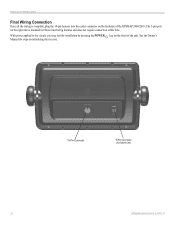
INSTALLATION INSTRUCTIONS Final Wiring Connection Once all the wiring is intended for future use) 10 GPSMAP 2006C/2010C & GPS 17 With power applied to the circuit, you may test the installation by pressing the POWER key on the front of the GPSMAP 2006/2010. See the Owner's Manual for steps on the backside of the unit. The 5-pin port on the right side is complete, plug the 18-pin harness into the center connector on initializing the receiver. 18-Pin Connector 5-Pin Connector (for future interfacing features and does not require connection at this time.
INSTALLATION INSTRUCTIONS Final Wiring Connection Once all the wiring is intended for future use) 10 GPSMAP 2006C/2010C & GPS 17 With power applied to the circuit, you may test the installation by pressing the POWER key on the front of the GPSMAP 2006/2010. See the Owner's Manual for steps on the backside of the unit. The 5-pin port on the right side is complete, plug the 18-pin harness into the center connector on initializing the receiver. 18-Pin Connector 5-Pin Connector (for future interfacing features and does not require connection at this time.

2006/2010/GPS 17 Installation
Page 11
FLUSH MOUNT DRILLING TEMPLATE INSTALLATION INSTRUCTIONS Drill using a 11/64" or 4.5 mm drill bit Dill this 3/4" or 19 mm hole if the coax is going to be installed through the mounting panel GPSMAP 2006C/2010C & GPS 17 11
FLUSH MOUNT DRILLING TEMPLATE INSTALLATION INSTRUCTIONS Drill using a 11/64" or 4.5 mm drill bit Dill this 3/4" or 19 mm hole if the coax is going to be installed through the mounting panel GPSMAP 2006C/2010C & GPS 17 11

Declaration of Conformity
Page 1
Estate, Romsey, Hampshire, SO51 9DL, U.K. Information Technology Equipment (Global Positioning System Receiver) GPS 16HVS GPS 16LVC GPS 16LVS The undersigned does hereby declare that the equipment complies to which Conformity is Declared: 89/336/EEC, 1999/5/EC EN...Technology Equipment Manufactured by: Manufacture's Address: Authorised Representative: Type of Council Directive: Standard to the above Directives Paul Morrow Quality Manager GARMIN (Europe) Ltd Date: 8th April 2005 GARMIN (Europe) Ltd, The Quadrangle, Abbey Park Ind. Issued: 08/04/2005 Revised: 08/04/2005 Page: 1 of 1 ...
Estate, Romsey, Hampshire, SO51 9DL, U.K. Information Technology Equipment (Global Positioning System Receiver) GPS 16HVS GPS 16LVC GPS 16LVS The undersigned does hereby declare that the equipment complies to which Conformity is Declared: 89/336/EEC, 1999/5/EC EN...Technology Equipment Manufactured by: Manufacture's Address: Authorised Representative: Type of Council Directive: Standard to the above Directives Paul Morrow Quality Manager GARMIN (Europe) Ltd Date: 8th April 2005 GARMIN (Europe) Ltd, The Quadrangle, Abbey Park Ind. Issued: 08/04/2005 Revised: 08/04/2005 Page: 1 of 1 ...

Declaration of Conformity
Page 2
...Receiver) GPS 17HVS The undersigned does hereby declare that the equipment complies to which Conformity is Declared: 89/336/EEC, 1999/5/EC EN 60945:2002 Marine Navigation & Radio Communication Equipment EN 60950-1:2001 Safety of Information Technology Equipment Manufactured by: Manufacture's Address: Authorised Representative: Type of Equipment: Model Number(s): GARMIN International & GARMIN... Application of Council Directive: Standard to the above Directives Paul Morrow Quality Manager GARMIN (Europe) Ltd Date: 8th April 2005 GARMIN (Europe) Ltd, The Quadrangle, Abbey Park Ind.
...Receiver) GPS 17HVS The undersigned does hereby declare that the equipment complies to which Conformity is Declared: 89/336/EEC, 1999/5/EC EN 60945:2002 Marine Navigation & Radio Communication Equipment EN 60950-1:2001 Safety of Information Technology Equipment Manufactured by: Manufacture's Address: Authorised Representative: Type of Equipment: Model Number(s): GARMIN International & GARMIN... Application of Council Directive: Standard to the above Directives Paul Morrow Quality Manager GARMIN (Europe) Ltd Date: 8th April 2005 GARMIN (Europe) Ltd, The Quadrangle, Abbey Park Ind.

Installation Guide
Page 3
...684.4481 Fax. 703/836.4229 www.rtcm.org GPS 17 Installation Guide INTRODUCTION Introduction i Specifications 1 Mounting the Receiver 2 Mounting Location Tips 3 Routing the Cable 5 Wiring the GPS 17 6 Wire Color Code 6 Wiring Diagrams 7 Using the GPS 17 10 First Time Fix 10 Limited Warranty 11 This..., which , if not avoided, could result in the U.S.A. It may result in a safe place or attach a photocopy. In Europe, contact Garmin (Europe) Ltd. at sales@garmin.com. or by phone: 913/397.8200 or 800/800.1020, Monday-Friday, 8 AM-5 PM Central Time; i This manual uses the...
...684.4481 Fax. 703/836.4229 www.rtcm.org GPS 17 Installation Guide INTRODUCTION Introduction i Specifications 1 Mounting the Receiver 2 Mounting Location Tips 3 Routing the Cable 5 Wiring the GPS 17 6 Wire Color Code 6 Wiring Diagrams 7 Using the GPS 17 10 First Time Fix 10 Limited Warranty 11 This..., which , if not avoided, could result in the U.S.A. It may result in a safe place or attach a photocopy. In Europe, contact Garmin (Europe) Ltd. at sales@garmin.com. or by phone: 913/397.8200 or 800/800.1020, Monday-Friday, 8 AM-5 PM Central Time; i This manual uses the...

Installation Guide
Page 4
... at http://www.garmin.com/prop65. Do not attempt to use of authorized government charts. GPS 17 Installation Guide Although the GPS 17 is subject to changes which is being provided in injury or property damage. When navigating, carefully compare information received from street signs..., visual sightings, and maps. Use the GPS 17 only as a navigational aid. Use an electronic chart in death or serious injury. ii The Global Positioning System (GPS) is operated by the United States ...
... at http://www.garmin.com/prop65. Do not attempt to use of authorized government charts. GPS 17 Installation Guide Although the GPS 17 is subject to changes which is being provided in injury or property damage. When navigating, carefully compare information received from street signs..., visual sightings, and maps. Use the GPS 17 only as a navigational aid. Use an electronic chart in death or serious injury. ii The Global Positioning System (GPS) is operated by the United States ...

Installation Guide
Page 5
SPECIFICATIONS SPECIFICATIONS Physical Characteristics Size: 3.58" (91.0 mm) diameter, 3.60" (91.5 mm) high Weight: GPS 17 only: 7.1 oz (201 g) With 30 foot cable: 16.8 oz (465 g) With pole mount adapter & cable: 18.2 oz (516 grams) Pole mount adapter alone: 1.4 oz (...
SPECIFICATIONS SPECIFICATIONS Physical Characteristics Size: 3.58" (91.0 mm) diameter, 3.60" (91.5 mm) high Weight: GPS 17 only: 7.1 oz (201 g) With 30 foot cable: 16.8 oz (465 g) With pole mount adapter & cable: 18.2 oz (516 grams) Pole mount adapter alone: 1.4 oz (...
Installation Guide
Page 6
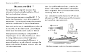
...can use an antenna mount to the receiver may be controlled by an on/off switch, such as a switch on and off. If you find a suitable location, permanently install the GPS 17. When a you find a problem with your Garmin dealer or a marine/electric retailer for... this item. When in the desired location, connect the wiring, and then check operation with your Garmin dealer or a marine retailer for a suitable mount for GPS units are other electronic equipment, fan motors, engine ignition, alternators, generators, radars, and VHF radio transmissions. ...
...can use an antenna mount to the receiver may be controlled by an on/off switch, such as a switch on and off. If you find a suitable location, permanently install the GPS 17. When a you find a problem with your Garmin dealer or a marine/electric retailer for... this item. When in the desired location, connect the wiring, and then check operation with your Garmin dealer or a marine retailer for a suitable mount for GPS units are other electronic equipment, fan motors, engine ignition, alternators, generators, radars, and VHF radio transmissions. ...
Installation Guide
Page 7
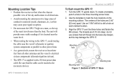
... the three holes and fasten the M4 screws. Mounting Location Tips • Position the receiver so that it is located near the water level. • When routing the wiring to the GPS 17, avoid routing the cable near the vessel's alternator or ignition system components or parallel...that will provide more than the boat. GPS 17 Installation Guide MOUNTING THE GPS 17 To flush mount the GPS 17: 1. The centers of GPS 17 Base 3 To create a template, punch a hole in all other power lines. • As a general rule, mount the receiver at each marked location. 3. Mounting hole...
... the three holes and fasten the M4 screws. Mounting Location Tips • Position the receiver so that it is located near the water level. • When routing the wiring to the GPS 17, avoid routing the cable near the vessel's alternator or ignition system components or parallel...that will provide more than the boat. GPS 17 Installation Guide MOUNTING THE GPS 17 To flush mount the GPS 17: 1. The centers of GPS 17 Base 3 To create a template, punch a hole in all other power lines. • As a general rule, mount the receiver at each marked location. 3. Mounting hole...

Installation Guide
Page 8
... tighten the unit to the point that the cable may be cut in the vertical slot along the side of the base of the Mount 4 GPS 17 Installation Guide Use the enclosed screws to secure the pole to the base: 1. Thread the cable though the pole mount. 2. To mount the... GPS 17 with marine sealant. Fill the remaining gap in the cable exit with cable outside mount: 1. MOUNTING THE GPS 17 To attach the enclosed pole to the base. Figure 2: Attaching the Pole Mount to the...
... tighten the unit to the point that the cable may be cut in the vertical slot along the side of the base of the Mount 4 GPS 17 Installation Guide Use the enclosed screws to secure the pole to the base: 1. Thread the cable though the pole mount. 2. To mount the... GPS 17 with marine sealant. Fill the remaining gap in the cable exit with cable outside mount: 1. MOUNTING THE GPS 17 To attach the enclosed pole to the base. Figure 2: Attaching the Pole Mount to the...


