
2006/2010/GPS 17 Installation
Page 4
... unit: 1. Using an appropriate size drill bit, drill pilot holes for the wiring. 2. Slide the unit into the bail mount and tighten the mounting knobs. Loosen the mounting knobs. 5. Mounting knobs Bail Mount Bail mount 4 GPSMAP 2006C/2010C & GPS 17 Be sure to the surface with the fasteners. 4. Secure the bail mount...
... unit: 1. Using an appropriate size drill bit, drill pilot holes for the wiring. 2. Slide the unit into the bail mount and tighten the mounting knobs. Loosen the mounting knobs. 5. Mounting knobs Bail Mount Bail mount 4 GPSMAP 2006C/2010C & GPS 17 Be sure to the surface with the fasteners. 4. Secure the bail mount...

2006/2010/GPS 17 Installation
Page 8
..., HORN, OR BOTH. Basic Hook-up showing the GPSMAP 2006/2010 (using the 18-pin wiring harness) interfacing with a variety of wire, 24 AWG (unless otherwise noted on wiring diagram), shielded, twisted-pair wiring is a simple hook-up WIRE COLOR GARMIN GPS 17 GPS SENSOR YELLOW ON 1A RED POWER BLACK BLUE WHITE GROUND COM 1 IN COM 1 OUT...
..., HORN, OR BOTH. Basic Hook-up showing the GPSMAP 2006/2010 (using the 18-pin wiring harness) interfacing with a variety of wire, 24 AWG (unless otherwise noted on wiring diagram), shielded, twisted-pair wiring is a simple hook-up WIRE COLOR GARMIN GPS 17 GPS SENSOR YELLOW ON 1A RED POWER BLACK BLUE WHITE GROUND COM 1 IN COM 1 OUT...
2006/2010/GPS 17 Installation
Page 10
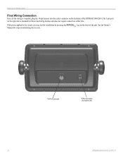
The 5-pin port on the right side is complete, plug the 18-pin harness into the center connector on the backside of the unit. See the Owner's Manual for steps on the front of the GPSMAP 2006/2010. With power applied to the circuit, you may test the installation by pressing the POWER key on initializing the receiver. 18-Pin Connector 5-Pin Connector (for future use) 10 GPSMAP 2006C/2010C & GPS 17 INSTALLATION INSTRUCTIONS Final Wiring Connection Once all the wiring is intended for future interfacing features and does not require connection at this time.
The 5-pin port on the right side is complete, plug the 18-pin harness into the center connector on the backside of the unit. See the Owner's Manual for steps on the front of the GPSMAP 2006/2010. With power applied to the circuit, you may test the installation by pressing the POWER key on initializing the receiver. 18-Pin Connector 5-Pin Connector (for future use) 10 GPSMAP 2006C/2010C & GPS 17 INSTALLATION INSTRUCTIONS Final Wiring Connection Once all the wiring is intended for future interfacing features and does not require connection at this time.

Installation Guide
Page 3
...4481 Fax. 703/836.4229 www.rtcm.org GPS 17 Installation Guide INTRODUCTION Introduction i Specifications 1 Mounting the Receiver 2 Mounting Location Tips 3 Routing the Cable 5 Wiring the GPS 17 6 Wire Color Code 6 Wiring Diagrams 7 Using the GPS 17 10 First Time Fix 10 Limited Warranty 11... symbol to indicate a potentially hazardous situation, which, if not avoided, could result in the U.S.A. contact Garmin® Product Support by e-mail at sales@garmin.com. Complete information concerning NMEA & RTCM formats and sentences is available for purchase at 44/0870.8501241....
...4481 Fax. 703/836.4229 www.rtcm.org GPS 17 Installation Guide INTRODUCTION Introduction i Specifications 1 Mounting the Receiver 2 Mounting Location Tips 3 Routing the Cable 5 Wiring the GPS 17 6 Wire Color Code 6 Wiring Diagrams 7 Using the GPS 17 10 First Time Fix 10 Limited Warranty 11... symbol to indicate a potentially hazardous situation, which, if not avoided, could result in the U.S.A. contact Garmin® Product Support by e-mail at sales@garmin.com. Complete information concerning NMEA & RTCM formats and sentences is available for purchase at 44/0870.8501241....
Installation Guide
Page 6
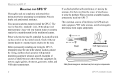
...nd a suitable location, permanently install the GPS 17. OK Radar BELOW- Before permanently installing and wiring the GPS 17, temporarily place the unit in doubt, seek professional assistance. You can use an antenna mount to the receiver may be controlled by an on/off switch...ABOVE- Power to install the GPS 17. MOUNTING THE GPS 17 MOUNTING THE GPS 17 Thoroughly read and completely understand these instructions before attempting the installation. When a you find a problem with your Garmin dealer or a marine/electric retailer for GPS units are other electronic equipment, ...
...nd a suitable location, permanently install the GPS 17. OK Radar BELOW- Before permanently installing and wiring the GPS 17, temporarily place the unit in doubt, seek professional assistance. You can use an antenna mount to the receiver may be controlled by an on/off switch...ABOVE- Power to install the GPS 17. MOUNTING THE GPS 17 MOUNTING THE GPS 17 Thoroughly read and completely understand these instructions before attempting the installation. When a you find a problem with your Garmin dealer or a marine/electric retailer for GPS units are other electronic equipment, ...
Installation Guide
Page 7
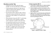
...from all other antennas and the vessel's electrical system components (alternator/ignition system). • The GPS 17 is located near the water level. • When routing the wiring to the GPS 17, avoid routing the cable near the vessel's alternator or ignition system components or parallel to other... power lines. • As a general rule, mount the receiver at each marked location. 3. Be sure that will provide...
...from all other antennas and the vessel's electrical system components (alternator/ignition system). • The GPS 17 is located near the water level. • When routing the wiring to the GPS 17, avoid routing the cable near the vessel's alternator or ignition system components or parallel to other... power lines. • As a general rule, mount the receiver at each marked location. 3. Be sure that will provide...

Installation Guide
Page 10
... for these items. 54 3 21 98 76 DB-9 Female Serial Connector 13 7 3 21 25 14 DB-25 Female Serial Connector Garmin recommends that the GPS 17 and the receiving device share the same ground. Check with a PC or electronics supplier for RTCM input only. Black: Ground (Power (-) and Data ...Output Gray: Pulse Per Second Output Green: Port 2 RTCM Data Input Violet: Port 2 RTCM Data Output (Not Used) 6 GPS 17 Installation Guide Wire Color Code Red: Power (+) 8-40 VDC. Wire the unit to its own circuit to your NMEA device or PC. You need a DB-9 or DB-25 serial connector (...
... for these items. 54 3 21 98 76 DB-9 Female Serial Connector 13 7 3 21 25 14 DB-25 Female Serial Connector Garmin recommends that the GPS 17 and the receiving device share the same ground. Check with a PC or electronics supplier for RTCM input only. Black: Ground (Power (-) and Data ...Output Gray: Pulse Per Second Output Green: Port 2 RTCM Data Input Violet: Port 2 RTCM Data Output (Not Used) 6 GPS 17 Installation Guide Wire Color Code Red: Power (+) 8-40 VDC. Wire the unit to its own circuit to your NMEA device or PC. You need a DB-9 or DB-25 serial connector (...
Installation Guide
Page 11
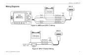
Wiring Diagrams Host Application NMEA Device Power Ground > Data Out Data In Power Source 8-40 Volts DC Fuse Red (Power) 1 A Black (Ground) Yellow (On/Off) Blue (Data In) > White (Data Out) > > Figure 5: NMEA and GPS 17 Wiring GPS 17 Closed = On Open = Off GPS 17 Installation Guide Power Source 8-40 Volts DC Fuse Red (Power) 1 A Black (Ground) Yellow (On/Off) Switch Figure 6: GPS 17 Switch Wiring WIRING THE GPS 17 GPS 17 7
Wiring Diagrams Host Application NMEA Device Power Ground > Data Out Data In Power Source 8-40 Volts DC Fuse Red (Power) 1 A Black (Ground) Yellow (On/Off) Blue (Data In) > White (Data Out) > > Figure 5: NMEA and GPS 17 Wiring GPS 17 Closed = On Open = Off GPS 17 Installation Guide Power Source 8-40 Volts DC Fuse Red (Power) 1 A Black (Ground) Yellow (On/Off) Switch Figure 6: GPS 17 Switch Wiring WIRING THE GPS 17 GPS 17 7

Installation Guide
Page 12
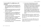
... Brown: Data In Blue: Data Out Black (Ground) Yellow (On/Off) White (Port 1 Data Out) Green (Port 2 Data In) Figure 7: DGPS GBR 21/23 and GPS 17 Wiring GPS 17 DB-9 Serial PC Connector* 1 2 3 4 5 6 7 8 9 Pin 5: Ground > Pin 3: Data Out Pin 2: Data In Power Source 8-40 Volts DC Fuse 1 A Red (Power) Black (Ground) Yellow...
... Brown: Data In Blue: Data Out Black (Ground) Yellow (On/Off) White (Port 1 Data Out) Green (Port 2 Data In) Figure 7: DGPS GBR 21/23 and GPS 17 Wiring GPS 17 DB-9 Serial PC Connector* 1 2 3 4 5 6 7 8 9 Pin 5: Ground > Pin 3: Data Out Pin 2: Data In Power Source 8-40 Volts DC Fuse 1 A Red (Power) Black (Ground) Yellow...
Installation Guide
Page 13
...devices is applied/removed to a power source but manually powered on page 7. When the Black and Yellow wires are combined, the GPS 17 will allow the GPS 17 to remain connected to the Red (+) wire. If the receiver is being installed, refer to Figure 6 on (pull down to less than 0.5 volts) and off ...when power is determined by the NMEA device. 4. If one of the NMEA device or to a ground. To wire the GPS 17 to it. Some non-Garmin devices may output data...
...devices is applied/removed to a power source but manually powered on page 7. When the Black and Yellow wires are combined, the GPS 17 will allow the GPS 17 to remain connected to the Red (+) wire. If the receiver is being installed, refer to Figure 6 on (pull down to less than 0.5 volts) and off ...when power is determined by the NMEA device. 4. If one of the NMEA device or to a ground. To wire the GPS 17 to it. Some non-Garmin devices may output data...
Technical Specifications
Page 3
... 1.7.1.5 Case Material...5 1.7.1.6 GPS 17HVS Thread Specifications 5 1.7.2 Electrical Characteristics ...5 1.7.2.1 Input Voltage ...5 1.7.2.2 Input Current ...5 1.7.2.3 Standby Current...5 1.7.2.4 GPS Receiver Sensitivity 5 1.7.3 Environmental Characteristics 5 1.7.4 GPS Performance...6 1.7.4.1 Receiver...6 1.7.4.2 Acquisition Times...6 1.7.4.3 Sentence Rate ...6 1.7.4.4 Accuracy...6 1.7.5 Interfaces...6 1.7.5.1 Port 1 ...6 1.7.5.2 Port 2 ...6 1.7.5.3 PPS ...6 1.7.5.4 Power Control...6 2 GPS 16/17 Wiring and Pinouts 7 2.1 GPS 16/17 Pinout ...7 2.2 GPS 16/17 Wiring Diagrams...8 3 Mechanical...
... 1.7.1.5 Case Material...5 1.7.1.6 GPS 17HVS Thread Specifications 5 1.7.2 Electrical Characteristics ...5 1.7.2.1 Input Voltage ...5 1.7.2.2 Input Current ...5 1.7.2.3 Standby Current...5 1.7.2.4 GPS Receiver Sensitivity 5 1.7.3 Environmental Characteristics 5 1.7.4 GPS Performance...6 1.7.4.1 Receiver...6 1.7.4.2 Acquisition Times...6 1.7.4.3 Sentence Rate ...6 1.7.4.4 Accuracy...6 1.7.5 Interfaces...6 1.7.5.1 Port 1 ...6 1.7.5.2 Port 2 ...6 1.7.5.3 PPS ...6 1.7.5.4 Power Control...6 2 GPS 16/17 Wiring and Pinouts 7 2.1 GPS 16/17 Pinout ...7 2.2 GPS 16/17 Wiring Diagrams...8 3 Mechanical...
Technical Specifications
Page 4
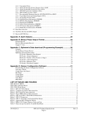
... Datums 20 Appendix B: Binary Phase Output Format 23 Position Record ...23 Receiver Measurement Record ...24 Sample C Code...25 Appendix C: Ephemeris Data download (Programming Example 26 Synopsis ...26 Garmin Binary Format Review ...26 Ephemeris Download Procedure ...27 TX Packet: Ephemeris ......32 Config Menu ...32 View Menu...33 Help Menu...33 LIST OF TABLES AND FIGURES GPS 16LVS & 16HVS ...4 GPS17HVS with Pole Mount ...4 GPS 17HVS Flush Mount ...4 Table 1: GPS 16/17 Wire Pinout ...7 Figure 1: Computer Serial Port Interconnection...8 Figure 2: PDA Serial Port Interconnection...8 Figure...
... Datums 20 Appendix B: Binary Phase Output Format 23 Position Record ...23 Receiver Measurement Record ...24 Sample C Code...25 Appendix C: Ephemeris Data download (Programming Example 26 Synopsis ...26 Garmin Binary Format Review ...26 Ephemeris Download Procedure ...27 TX Packet: Ephemeris ......32 Config Menu ...32 View Menu...33 Help Menu...33 LIST OF TABLES AND FIGURES GPS 16LVS & 16HVS ...4 GPS17HVS with Pole Mount ...4 GPS 17HVS Flush Mount ...4 Table 1: GPS 16/17 Wire Pinout ...7 Figure 1: Computer Serial Port Interconnection...8 Figure 2: PDA Serial Port Interconnection...8 Figure...
Technical Specifications
Page 11
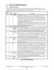
2 GPS 16/17 WIRING AND PINOUTS 2.1 GPS 16/17 Pinout The GPS 16LVS and GPS 16HVS sensors utilize an 8-pin RJ-45 plug. The following is switchable in the GPS 16HVS and GPS 17HVS. GPS 16HVS & GPS 17HVS: Vin can remove the JST connector without voiding your warranty. Typical operating power is a...Input. This input may also be used to 38400 baud. The NMEA 0183 baud rate is a functional description of 300 to receive serial differential GPS data formatted per NMEA 0183, Version 3.0. One-Pulse-Per-Second Output. Open circuit output voltage is 2.4 V. Second Serial Asynchronous...
2 GPS 16/17 WIRING AND PINOUTS 2.1 GPS 16/17 Pinout The GPS 16LVS and GPS 16HVS sensors utilize an 8-pin RJ-45 plug. The following is switchable in the GPS 16HVS and GPS 17HVS. GPS 16HVS & GPS 17HVS: Vin can remove the JST connector without voiding your warranty. Typical operating power is a...Input. This input may also be used to 38400 baud. The NMEA 0183 baud rate is a functional description of 300 to receive serial differential GPS data formatted per NMEA 0183, Version 3.0. One-Pulse-Per-Second Output. Open circuit output voltage is 2.4 V. Second Serial Asynchronous...
Technical Specifications
Page 12
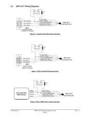
A 2.2 GPS 16/17 Wiring Diagrams Figure 1: Computer Serial Port Interconnection Figure 2: PDA Serial Port Interconnection 190-00228-21 Figure 3: Basic NMEA Device Interconnection GPS 16/17 Technical Specifications Page 8 Rev.
A 2.2 GPS 16/17 Wiring Diagrams Figure 1: Computer Serial Port Interconnection Figure 2: PDA Serial Port Interconnection 190-00228-21 Figure 3: Basic NMEA Device Interconnection GPS 16/17 Technical Specifications Page 8 Rev.

Technical Specifications
Page 23
...the signal is synchronized to the start of the one-pulse-per-second output is maintained only while the GPS sensor can be received by the GPS 16/17 series products on the SC-104 format, refer to RTCM Paper 134-89/SC 104-68 ... Distance to the pulse immediately preceding the NMEA 0183 RMC sentence. The signal is referenced to beacon reference station in kilometers Beacon receiver communication status (0 = Check Wiring, 1 = No Signal, 2 = Tuning, 3 = Receiving, 4= Scanning) DGPS fix source (R = RTCM, W = WAAS, N = Non-DGPS Fix) DGPS mode, A = Automatic, W = WAAS Only, R = RTCM Only, N =...
...the signal is synchronized to the start of the one-pulse-per-second output is maintained only while the GPS sensor can be received by the GPS 16/17 series products on the SC-104 format, refer to RTCM Paper 134-89/SC 104-68 ... Distance to the pulse immediately preceding the NMEA 0183 RMC sentence. The signal is referenced to beacon reference station in kilometers Beacon receiver communication status (0 = Check Wiring, 1 = No Signal, 2 = Tuning, 3 = Receiving, 4= Scanning) DGPS fix source (R = RTCM, W = WAAS, N = Non-DGPS Fix) DGPS mode, A = Automatic, W = WAAS Only, R = RTCM Only, N =...

