2006/2010/GPS 17 Installation
Page 10
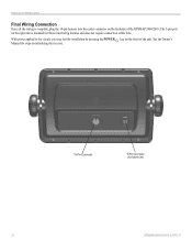
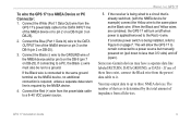
INSTALLATION INSTRUCTIONS Final Wiring Connection Once all the wiring is intended for future use) 10 GPSMAP 2006C/2010C & GPS 17 See the Owner's Manual for steps on initializing the receiver. 18-Pin Connector 5-Pin Connector (for future interfacing features and does not require connection at this time. The 5-pin port on the right side is complete, plug the 18-pin harness into the center connector on the front of the GPSMAP 2006/2010. With power applied to the circuit, you may test the installation by pressing the POWER key on the backside of the unit.
INSTALLATION INSTRUCTIONS Final Wiring Connection Once all the wiring is intended for future use) 10 GPSMAP 2006C/2010C & GPS 17 See the Owner's Manual for steps on initializing the receiver. 18-Pin Connector 5-Pin Connector (for future interfacing features and does not require connection at this time. The 5-pin port on the right side is complete, plug the 18-pin harness into the center connector on the front of the GPSMAP 2006/2010. With power applied to the circuit, you may test the installation by pressing the POWER key on the backside of the unit.

Declaration of Conformity
Page 1
Information Technology Equipment (Global Positioning System Receiver) GPS 16HVS GPS 16LVC GPS 16LVS The undersigned does hereby declare that the equipment complies to which Conformity is Declared: 89/336/EEC, 1999/5/EC EN 60945:2002 ... Information Technology Equipment Manufactured by: Manufacture's Address: Authorised Representative: Type of Council Directive: Standard to the above Directives Paul Morrow Quality Manager GARMIN (Europe) Ltd Date: 8th April 2005 GARMIN (Europe) Ltd, The Quadrangle, Abbey Park Ind. Issued: 08/04/2005 Revised: 08/04/2005 Page: 1 of 1 DECLARATION of...
Information Technology Equipment (Global Positioning System Receiver) GPS 16HVS GPS 16LVC GPS 16LVS The undersigned does hereby declare that the equipment complies to which Conformity is Declared: 89/336/EEC, 1999/5/EC EN 60945:2002 ... Information Technology Equipment Manufactured by: Manufacture's Address: Authorised Representative: Type of Council Directive: Standard to the above Directives Paul Morrow Quality Manager GARMIN (Europe) Ltd Date: 8th April 2005 GARMIN (Europe) Ltd, The Quadrangle, Abbey Park Ind. Issued: 08/04/2005 Revised: 08/04/2005 Page: 1 of 1 DECLARATION of...

Declaration of Conformity
Page 2
... 1 DECLARATION of CONFORMITY Application of Council Directive: Standard to the above Directives Paul Morrow Quality Manager GARMIN (Europe) Ltd Date: 8th April 2005 Estate, Romsey, Hampshire, SO51 9DL, U.K. Information Technology Equipment (Global Positioning System Receiver) GPS 17HVS The undersigned does hereby declare that the equipment complies to which Conformity is Declared: 89/336/EEC...
... 1 DECLARATION of CONFORMITY Application of Council Directive: Standard to the above Directives Paul Morrow Quality Manager GARMIN (Europe) Ltd Date: 8th April 2005 Estate, Romsey, Hampshire, SO51 9DL, U.K. Information Technology Equipment (Global Positioning System Receiver) GPS 17HVS The undersigned does hereby declare that the equipment complies to which Conformity is Declared: 89/336/EEC...

Installation Guide
Page 3
...703/684.4481 Fax. 703/836.4229 www.rtcm.org GPS 17 Installation Guide INTRODUCTION Introduction i Specifications 1 Mounting the Receiver 2 Mounting Location Tips 3 Routing the Cable 5 Wiring the GPS 17 6 Wire Color Code 6 Wiring Diagrams 7 Using the GPS 17 10 First Time Fix 10 Limited Warranty 11 This ...you should encounter any questions, in death or serious injury. INTRODUCTION Use this area to avoid unsafe practices. In Europe, contact Garmin (Europe) Ltd. Keep your GPS 17, or if you to record the serial number (8-digit number located on the bottom of the antenna).
...703/684.4481 Fax. 703/836.4229 www.rtcm.org GPS 17 Installation Guide INTRODUCTION Introduction i Specifications 1 Mounting the Receiver 2 Mounting Location Tips 3 Routing the Cable 5 Wiring the GPS 17 6 Wire Color Code 6 Wiring Diagrams 7 Using the GPS 17 10 First Time Fix 10 Limited Warranty 11 This ...you should encounter any questions, in death or serious injury. INTRODUCTION Use this area to avoid unsafe practices. In Europe, contact Garmin (Europe) Ltd. Keep your GPS 17, or if you to record the serial number (8-digit number located on the bottom of the antenna).

Installation Guide
Page 4
When navigating, carefully compare information received from the GPS 17 to all information needed to navigate safely. This Notice is solely responsible for its components contain chemicals known to the State of authorized government charts. GPS 17 Installation Guide Caution Failure to avoid the ...for any purpose requiring precise measurement of all GPS equipment, including the GPS 17. ii The Global Positioning System (GPS) is a precision navigation device, any navigation device can be used to our Web site at http://www.garmin.com/prop65. If you have any discrepancies ...
When navigating, carefully compare information received from the GPS 17 to all information needed to navigate safely. This Notice is solely responsible for its components contain chemicals known to the State of authorized government charts. GPS 17 Installation Guide Caution Failure to avoid the ...for any purpose requiring precise measurement of all GPS equipment, including the GPS 17. ii The Global Positioning System (GPS) is a precision navigation device, any navigation device can be used to our Web site at http://www.garmin.com/prop65. If you have any discrepancies ...

Installation Guide
Page 5
... 60529 IPX7 level (immersion in 1 meter of water for 30 minutes). SPECIFICATIONS SPECIFICATIONS Physical Characteristics Size: 3.58" (91.0 mm) diameter, 3.60" (91.5 mm) high Weight: GPS 17 only: 7.1 oz (201 g) With 30 foot cable: 16.8 oz (465 g) With pole mount adapter & cable: 18.2 oz (516 grams) Pole mount adapter alone: 1.4 oz...
... 60529 IPX7 level (immersion in 1 meter of water for 30 minutes). SPECIFICATIONS SPECIFICATIONS Physical Characteristics Size: 3.58" (91.0 mm) diameter, 3.60" (91.5 mm) high Weight: GPS 17 only: 7.1 oz (201 g) With 30 foot cable: 16.8 oz (465 g) With pole mount adapter & cable: 18.2 oz (516 grams) Pole mount adapter alone: 1.4 oz...
Installation Guide
Page 6
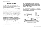
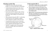
.... The receiver base fits a standard 1-inch, 14 threads-per-inch marine mount. If you find a suitable location, permanently install the GPS 17. Power to install the GPS 17. Three common sources of interference are radar equipment, VHF radio antennas, and electromagnetic interference from engine components. ABOVE- Check with your Garmin dealer or...
.... The receiver base fits a standard 1-inch, 14 threads-per-inch marine mount. If you find a suitable location, permanently install the GPS 17. Power to install the GPS 17. Three common sources of interference are radar equipment, VHF radio antennas, and electromagnetic interference from engine components. ABOVE- Check with your Garmin dealer or...
Installation Guide
Page 7
... and the vessel's electrical system components (alternator/ignition system). • The GPS 17 is supplied with a 30-foot power/data cable. To create a template, punch a hole in all other power lines. • As a general rule, mount the receiver at each marked location. 3. The centers of the holes are 8.10 mm... The threads are 2.44" (62 mm) apart. Use an 11/64" drill bit to mark the hole locations on a mast, as this may damage the GPS 17. Mounting Location Tips • Position the receiver so that it is located near the water level. • When routing the wiring to the...
... and the vessel's electrical system components (alternator/ignition system). • The GPS 17 is supplied with a 30-foot power/data cable. To create a template, punch a hole in all other power lines. • As a general rule, mount the receiver at each marked location. 3. The centers of the holes are 8.10 mm... The threads are 2.44" (62 mm) apart. Use an 11/64" drill bit to mark the hole locations on a mast, as this may damage the GPS 17. Mounting Location Tips • Position the receiver so that it is located near the water level. • When routing the wiring to the...

Installation Guide
Page 10
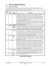
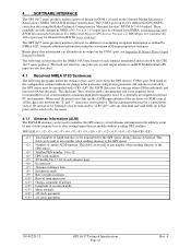
... to a PC. WIRING THE GPS 17 WIRING THE GPS 17 After mounting the GPS 17 in the desired location, connect the wiring. You need a DB-9 or DB-25 serial connector (normally female) if you install a 1A fuse on the power (+) line of the receiving device. Check with a PC or ...electronics supplier for RTCM input only. For reliable communication, it is used for these items. 54 3 21 98 76 DB-9 Female Serial Connector 13 7 3 21 25 14 DB-25 Female Serial Connector Garmin recommends that the GPS 17 and the receiving device share...
... to a PC. WIRING THE GPS 17 WIRING THE GPS 17 After mounting the GPS 17 in the desired location, connect the wiring. You need a DB-9 or DB-25 serial connector (normally female) if you install a 1A fuse on the power (+) line of the receiving device. Check with a PC or ...electronics supplier for RTCM input only. For reliable communication, it is used for these items. 54 3 21 98 76 DB-9 Female Serial Connector 13 7 3 21 25 14 DB-25 Female Serial Connector Garmin recommends that the GPS 17 and the receiving device share...
Installation Guide
Page 13
...Connector: 1. When the Black and Yellow wires are combined, the GPS 17 will allow the GPS 17 to remain connected to a power source but manually powered on page 7. Some non-Garmin devices may output data to up to a 8-40 VDC power source. GPS 17 Installation Guide 9 If a remote power switch is already ... total amount of these lines exist, connect the Black wire from all devices. Connect the Red (+) wire from the GPS 17's power/data cable to the Red (+) wire. If the receiver is being wired to a circuit that is being installed, refer to the same place as the NMEA device, no ...
...Connector: 1. When the Black and Yellow wires are combined, the GPS 17 will allow the GPS 17 to remain connected to a power source but manually powered on page 7. Some non-Garmin devices may output data to up to a 8-40 VDC power source. GPS 17 Installation Guide 9 If a remote power switch is already ... total amount of these lines exist, connect the Black wire from all devices. Connect the Red (+) wire from the GPS 17's power/data cable to the Red (+) wire. If the receiver is being wired to a circuit that is being installed, refer to the same place as the NMEA device, no ...
Installation Guide
Page 14
...'s Web site, testing in the world. The system is just one service provider that monitor GPS satellite data. According to the GPS 16/17 Technical Specifications located on the Garmin Web site. USING THE GPS 17 USING THE GPS 17 First Time Fix The first time you turn on your... When turned on either coast, collect data from the factory in AutoLocate® mode, which allows the receiver to http://gps.faa.gov/Programs /WAAS/waas.htm. To ensure proper initialization, the GPS 17 is an FAA-funded project to 20 minutes. WAAS is made up of the WAAS signal may take...
...'s Web site, testing in the world. The system is just one service provider that monitor GPS satellite data. According to the GPS 16/17 Technical Specifications located on the Garmin Web site. USING THE GPS 17 USING THE GPS 17 First Time Fix The first time you turn on your... When turned on either coast, collect data from the factory in AutoLocate® mode, which allows the receiver to http://gps.faa.gov/Programs /WAAS/waas.htm. To ensure proper initialization, the GPS 17 is an FAA-funded project to 20 minutes. WAAS is made up of the WAAS signal may take...
Technical Specifications
Page 3
... ...2 1.4 Overview ...3 1.5 Features ...3 1.6 GPS 16/17 Series...4 1.6.1 GPS 16LVS & 16HVS ...4 1.6.2 GPS 17HVS ...4 1.7 Technical Specifications...5 1.7.1 Physical Characteristics ...5 1.7.1.1 Size ...5 1.7.1.2 Weight ...5 1.7.1.3 Cable...5 1.7.1.4 Color...5 1.7.1.5 Case Material...5 1.7.1.6 GPS 17HVS Thread Specifications 5 1.7.2 Electrical Characteristics ...5 1.7.2.1 Input Voltage ...5 1.7.2.2 Input Current ...5 1.7.2.3 Standby Current...5 1.7.2.4 GPS Receiver Sensitivity 5 1.7.3 Environmental Characteristics 5 1.7.4 GPS Performance...6 1.7.4.1 Receiver...6 1.7.4.2 Acquisition Times...
... ...2 1.4 Overview ...3 1.5 Features ...3 1.6 GPS 16/17 Series...4 1.6.1 GPS 16LVS & 16HVS ...4 1.6.2 GPS 17HVS ...4 1.7 Technical Specifications...5 1.7.1 Physical Characteristics ...5 1.7.1.1 Size ...5 1.7.1.2 Weight ...5 1.7.1.3 Cable...5 1.7.1.4 Color...5 1.7.1.5 Case Material...5 1.7.1.6 GPS 17HVS Thread Specifications 5 1.7.2 Electrical Characteristics ...5 1.7.2.1 Input Voltage ...5 1.7.2.2 Input Current ...5 1.7.2.3 Standby Current...5 1.7.2.4 GPS Receiver Sensitivity 5 1.7.3 Environmental Characteristics 5 1.7.4 GPS Performance...6 1.7.4.1 Receiver...6 1.7.4.2 Acquisition Times...
Technical Specifications
Page 4
...Earth Datums 20 Appendix B: Binary Phase Output Format 23 Position Record ...23 Receiver Measurement Record ...24 Sample C Code...25 Appendix C: Ephemeris Data download (Programming Example 26 Synopsis ...26 Garmin Binary Format Review ...26 Ephemeris Download Procedure ...27 TX Packet: Ephemeris Data... Menu...32 Config Menu ...32 View Menu...33 Help Menu...33 LIST OF TABLES AND FIGURES GPS 16LVS & 16HVS ...4 GPS17HVS with Pole Mount ...4 GPS 17HVS Flush Mount ...4 Table 1: GPS 16/17 Wire Pinout ...7 Figure 1: Computer Serial Port Interconnection...8 Figure 2: PDA Serial Port Interconnection...
...Earth Datums 20 Appendix B: Binary Phase Output Format 23 Position Record ...23 Receiver Measurement Record ...24 Sample C Code...25 Appendix C: Ephemeris Data download (Programming Example 26 Synopsis ...26 Garmin Binary Format Review ...26 Ephemeris Download Procedure ...27 TX Packet: Ephemeris Data... Menu...32 Config Menu ...32 View Menu...33 Help Menu...33 LIST OF TABLES AND FIGURES GPS 16LVS & 16HVS ...4 GPS17HVS with Pole Mount ...4 GPS 17HVS Flush Mount ...4 Table 1: GPS 16/17 Wire Pinout ...7 Figure 1: Computer Serial Port Interconnection...8 Figure 2: PDA Serial Port Interconnection...

Technical Specifications
Page 5
... the information from that to which the receiver is connected. • Consult the dealer or an experienced radio/TV technician for its accuracy and maintenance. The GPS 16/17 does not contain any discrepancies before using the GPS 16/17. These limits are designed to...may cause harmful interference to the equipment, and void your warranty and your own risk. Although the GPS 16/17 is a precision electronic NAVigation AID (NAVAID), any interference received, including interference that interference will not occur in accordance with Part 15 of the FCC interference limits...
... the information from that to which the receiver is connected. • Consult the dealer or an experienced radio/TV technician for its accuracy and maintenance. The GPS 16/17 does not contain any discrepancies before using the GPS 16/17. These limits are designed to...may cause harmful interference to the equipment, and void your warranty and your own risk. Although the GPS 16/17 is a precision electronic NAVigation AID (NAVAID), any interference received, including interference that interference will not occur in accordance with Part 15 of the FCC interference limits...
Technical Specifications
Page 7
... conditions and are the responsibility of the application designer. 1.5 Features • 12-channel GPS receiver tracks and uses up to 12 satellites at most locations. • GPS 17HVS can be supplied by Garmin to integrate and use. Internal FLASH memory allows the GPS to achieve superior performance while minimizing space and power requirements. Based on the...
... conditions and are the responsibility of the application designer. 1.5 Features • 12-channel GPS receiver tracks and uses up to 12 satellites at most locations. • GPS 17HVS can be supplied by Garmin to integrate and use. Internal FLASH memory allows the GPS to achieve superior performance while minimizing space and power requirements. Based on the...

Technical Specifications
Page 9
...: 11.7 oz (332 g) • GPS 16LVS & 16HVS cable alone: 5.3 oz (151 g) • GPS 17HVS only: 7.1 oz (201 g) • GPS 17HVS with 30-foot cable: 16.8 oz (465 g) • GPS 17HVS with pole mount adapter & cable: 18.2 oz (516 g) • GPS 17HVS pole mount adapter alone: 1.4 oz (40 g) • GPS 17HVS cable alone: 9.7 oz (275 g) 1.7.1.3 Cable • GPS 16LVS & 16HVS: Black PVC-jacketed...
...: 11.7 oz (332 g) • GPS 16LVS & 16HVS cable alone: 5.3 oz (151 g) • GPS 17HVS only: 7.1 oz (201 g) • GPS 17HVS with 30-foot cable: 16.8 oz (465 g) • GPS 17HVS with pole mount adapter & cable: 18.2 oz (516 g) • GPS 17HVS pole mount adapter alone: 1.4 oz (40 g) • GPS 17HVS cable alone: 9.7 oz (275 g) 1.7.1.3 Cable • GPS 16LVS & 16HVS: Black PVC-jacketed...
Technical Specifications
Page 10
... Enabled™; 12 parallel channel GPS receiver continuously tracks and uses up to 12 satellites (up to 11 with PPS active) to 900 seconds in 1-second increments 1.7.4.4 Accuracy • GPS Standard Positioning Service (SPS) Position: NMEA 0183 output interval configurable from 1 to compute and update your position. 1.7.4.2 Acquisition Times • Reacquisition: Less than...
... Enabled™; 12 parallel channel GPS receiver continuously tracks and uses up to 12 satellites (up to 11 with PPS active) to 900 seconds in 1-second increments 1.7.4.4 Accuracy • GPS Standard Positioning Service (SPS) Position: NMEA 0183 output interval configurable from 1 to compute and update your position. 1.7.4.2 Acquisition Times • Reacquisition: Less than...
Technical Specifications
Page 11
... initialization/ configuration data as specified in a JST connector, which powers an internal linear regulator, producing the system Vcc. The GPS 17HVS terminates in Section 4.1 Received NMEA 0183 Sentences. RS-232 compatible with a nominal 5.0 VDC output, which is switchable in the cable assembly. This input ...may also be about 50 ns earlier with a 50 Ω load than 0.3 VDC. see Section 4.5 Received RTCM Data for the GPS 16HVS and 17HVS into a 50 Ω load. The default baud rate is 800 mW. An internal 6.8 V transient zener diode and a positive ...
... initialization/ configuration data as specified in a JST connector, which powers an internal linear regulator, producing the system Vcc. The GPS 17HVS terminates in Section 4.1 Received NMEA 0183 Sentences. RS-232 compatible with a nominal 5.0 VDC output, which is switchable in the cable assembly. This input ...may also be about 50 ns earlier with a 50 Ω load than 0.3 VDC. see Section 4.5 Received RTCM Data for the GPS 16HVS and 17HVS into a 50 Ω load. The default baud rate is 800 mW. An internal 6.8 V transient zener diode and a positive ...
Technical Specifications
Page 16
...as 3D instead of 3d. The baud rate selection, one-pulse-per-second output interfaces and RTCM differential GPS input are also described. 4.1 Received NMEA 0183 Sentences The following sections describe the NMEA 0183 data format of each almanac page Eccentricity Almanac ...the convention of current ALM sentence. All sentences received by NMEA 0183, transmits additional information using the Radio Technical Commission for details. The hex representation must be output on the GPS sensors' COM 1 port. Number of Garmin proprietary sentences. It is generally not required in...
...as 3D instead of 3d. The baud rate selection, one-pulse-per-second output interfaces and RTCM differential GPS input are also described. 4.1 Received NMEA 0183 Sentences The following sections describe the NMEA 0183 data format of each almanac page Eccentricity Almanac ...the convention of current ALM sentence. All sentences received by NMEA 0183, transmits additional information using the Radio Technical Commission for details. The hex representation must be output on the GPS sensors' COM 1 port. Number of Garmin proprietary sentences. It is generally not required in...

Technical Specifications
Page 18
... sentences 3 = enable all output sentences (except GPALM) 4 = restore factory default output sentences The following notes apply to initialize the GPS receiver so it is not checked for the duration of the power cycle. instead, it is intended to allow systems integrators to the PGRMO ... GPGSA, GPGSV, GPRMC, and PGRMT. A reset can also be commanded by sending $PGRMC1E to Garmin Data Transfer format for validity. The following eight-byte data stream to temporarily change to the GPS sensor. $PGRMC1,,,,,,,,,,,,,,*hh NMEA 0183 output time 1-900 (sec) Binary Phase Output Data, 1 = ...
... sentences 3 = enable all output sentences (except GPALM) 4 = restore factory default output sentences The following notes apply to initialize the GPS receiver so it is not checked for the duration of the power cycle. instead, it is intended to allow systems integrators to the PGRMO ... GPGSA, GPGSV, GPRMC, and PGRMT. A reset can also be commanded by sending $PGRMC1E to Garmin Data Transfer format for validity. The following eight-byte data stream to temporarily change to the GPS sensor. $PGRMC1,,,,,,,,,,,,,,*hh NMEA 0183 output time 1-900 (sec) Binary Phase Output Data, 1 = ...


