

Important Safety and Product Information
Page 2
... radio communications if not installed and used by turning the equipment off and on the Software. Limited Warranty THIS LIMITED WARRANTY GIVES YOU SPECIFIC LEGAL RIGHTS, AND YOU MAY HAVE OTHER LEGAL RIGHTS, WHICH VARY FROM STATE TO STATE (OR BY COUNTRY OR PROVINCE). Such repairs or replacement will be unable to service your product in which source code...
... radio communications if not installed and used by turning the equipment off and on the Software. Limited Warranty THIS LIMITED WARRANTY GIVES YOU SPECIFIC LEGAL RIGHTS, AND YOU MAY HAVE OTHER LEGAL RIGHTS, WHICH VARY FROM STATE TO STATE (OR BY COUNTRY OR PROVINCE). Such repairs or replacement will be unable to service your product in which source code...
Installation Instructions
Page 1
... operated, the use of this radar conforms to the requirements of the body to your chartplotter owner's manual at close range when the radar is installed according to Radio Frequency Electromagnetic Fields. This device should be opened only by fire or overheating, the appropriate fuse must update the Garmin chartplotter software when you install this device according to these instructions and that...
... operated, the use of this radar conforms to the requirements of the body to your chartplotter owner's manual at close range when the radar is installed according to Radio Frequency Electromagnetic Fields. This device should be opened only by fire or overheating, the appropriate fuse must update the Garmin chartplotter software when you install this device according to these instructions and that...

Installation Instructions
Page 2
Tools Needed • #2 Phillips screwdriver • 5 mm hex wrench • Drill and 15.0 mm (19/32 in.) drill bit • 17 mm (21/32 in.) wrench and torque wrench • A length of 3.31 mm² (12 AWG) copper wire to ground the radar housing (and voltage converter, if applicable). • Marine sealant 2
Tools Needed • #2 Phillips screwdriver • 5 mm hex wrench • Drill and 15.0 mm (19/32 in.) drill bit • 17 mm (21/32 in.) wrench and torque wrench • A length of 3.31 mm² (12 AWG) copper wire to ground the radar housing (and voltage converter, if applicable). • Marine sealant 2
Installation Instructions
Page 3
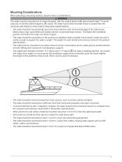
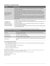
... specifications. • The radar should be mounted out of range of the radar beam. Shims can be mounted on a flat surface or a platform that is parallel to support the radar's weight. Mounting Considerations When selecting a mounting location, observe these considerations. • WARNING The radar must be mounted at least 2 m (6.5 ft.) away from cables carrying radio signals such as VHF radios, cables, and antennas. • The radar...
... specifications. • The radar should be mounted out of range of the radar beam. Shims can be mounted on a flat surface or a platform that is parallel to support the radar's weight. Mounting Considerations When selecting a mounting location, observe these considerations. • WARNING The radar must be mounted at least 2 m (6.5 ft.) away from cables carrying radio signals such as VHF radios, cables, and antennas. • The radar...

Installation Instructions
Page 4
... Radar for Mounting Before you can mount the radar, you must choose a suitable mounting location (Mounting Considerations, page 3). 1 Secure the included mounting template to the surface at the mounting location, along the bow-stern axis, as indicated on the template. 2 Drill the mounting holes using a 15 mm (19/32 in.) drill bit. 3 If you need to run the power and network cables...
... Radar for Mounting Before you can mount the radar, you must choose a suitable mounting location (Mounting Considerations, page 3). 1 Secure the included mounting template to the surface at the mounting location, along the bow-stern axis, as indicated on the template. 2 Drill the mounting holes using a 15 mm (19/32 in.) drill bit. 3 If you need to run the power and network cables...

Installation Instructions
Page 5
...using a 5 mm hex wrench. Mounting the Radar Before you can mount the radar, you must adjust the front-of-boat offset on the chartplotter to mount facing the bow along the bow-stern axis. If the hatch side is facing the bow, you should stop tightening the threaded rods when they no longer turn... easily. To avoid damaging the pedestal, you must first select a mounting location, and prepare the mounting surface and the radar (Preparing the Surface and the Radar for Mounting, page 4). 1 Take note of which end of the ...
...using a 5 mm hex wrench. Mounting the Radar Before you can mount the radar, you must adjust the front-of-boat offset on the chartplotter to mount facing the bow along the bow-stern axis. If the hatch side is facing the bow, you should stop tightening the threaded rods when they no longer turn... easily. To avoid damaging the pedestal, you must first select a mounting location, and prepare the mounting surface and the radar (Preparing the Surface and the Radar for Mounting, page 4). 1 Take note of which end of the ...

Installation Instructions
Page 6
3 From under the mounting surface, place the shoulder washers on the threaded rods and feed them into the mounting surface so they fit securely. 4 Place the flat washers , lock washers , and hex nuts on the threaded rods. 5 Torque the hex nuts to 1.5 kgf-m (130 lbf-in. [11 lbf-ft.]) to securely fasten the radar to the surface without damaging the radar or the mounting hardware. 6
3 From under the mounting surface, place the shoulder washers on the threaded rods and feed them into the mounting surface so they fit securely. 4 Place the flat washers , lock washers , and hex nuts on the threaded rods. 5 Torque the hex nuts to 1.5 kgf-m (130 lbf-in. [11 lbf-ft.]) to securely fasten the radar to the surface without damaging the radar or the mounting hardware. 6

Installation Instructions
Page 7
Installing the Antenna Before you can install the antenna on the pedestal, you must securely mount the pedestal (Mounting the Radar, page 5). 1 Remove the protective cover from the bottom of the antenna , and slide the antenna onto the pedestal. 7 These screws and washers are used to secure the antenna to the pedestal. 3 Align the waveguide on the pedestal with the socket on the top of the pedestal. 2 Remove the mounting hardware from the waveguide on the bottom of the antenna .
Installing the Antenna Before you can install the antenna on the pedestal, you must securely mount the pedestal (Mounting the Radar, page 5). 1 Remove the protective cover from the bottom of the antenna , and slide the antenna onto the pedestal. 7 These screws and washers are used to secure the antenna to the pedestal. 3 Align the waveguide on the pedestal with the socket on the top of the pedestal. 2 Remove the mounting hardware from the waveguide on the bottom of the antenna .
Installation Instructions
Page 8
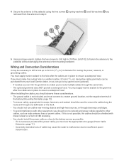
...the mounting hardware. If you must use the appropriate wire gauge (Power Cable Extensions, page 11). ◦ Incorrectly extended runs of EMI shielding. • You should not run network and power cables parallel to other cables,...used to secure the cable along the route and through any bulkheads or the deck. • You should install the power cable as close to the battery source as radio antenna lines or power cables. You must apply marine sealant to the hole after the cables are in place to ensure a waterproof seal. When installing the cables, you removed from your local Garmin...
...the mounting hardware. If you must use the appropriate wire gauge (Power Cable Extensions, page 11). ◦ Incorrectly extended runs of EMI shielding. • You should not run network and power cables parallel to other cables,...used to secure the cable along the route and through any bulkheads or the deck. • You should install the power cable as close to the battery source as radio antenna lines or power cables. You must apply marine sealant to the hole after the cables are in place to ensure a waterproof seal. When installing the cables, you removed from your local Garmin...
Installation Instructions
Page 9
...; You should install the voltage converter as close as indicated in -line fuse holder. Using a voltage converter with a voltage converter, it from your local Garmin dealer or you can go to the battery is not packaged with the radar, or the correct converter purchased from Garmin or from turning on. Connecting the power cable without the appropriate fuse in order for...
...; You should install the voltage converter as close as indicated in -line fuse holder. Using a voltage converter with a voltage converter, it from your local Garmin dealer or you can go to the battery is not packaged with the radar, or the correct converter purchased from Garmin or from turning on. Connecting the power cable without the appropriate fuse in order for...
Installation Instructions
Page 10
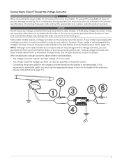
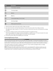
... the power cable, do not remove the in the radar power cable. Using a voltage converter with a voltage converter, you should connect it directly to buy.garmin.com. Item Description To the Garmin network 15 A fuse holder Red (+) Black (-) To the boat battery (10 to 32 Vdc) 30 A fuse holder Water ground connection 1 Route the power cable to the radar and the voltage converter. 2 Use crimp...
... the power cable, do not remove the in the radar power cable. Using a voltage converter with a voltage converter, you should connect it directly to buy.garmin.com. Item Description To the Garmin network 15 A fuse holder Red (+) Black (-) To the boat battery (10 to 32 Vdc) 30 A fuse holder Water ground connection 1 Route the power cable to the radar and the voltage converter. 2 Use crimp...
Installation Instructions
Page 11
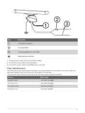
... To the Garmin network 15 A fuse holder To the boat battery (11 to 32 Vdc) Water ground connection 1 Route the power cable to the radar and boat battery. 2 Connect the power cable to the boat battery. 3 Connect the power cable to create a water-resistant connection. Power Cable Extensions Connecting the power cable directly to the battery is necessary to extend the cable, the appropriate gauge of wire must use crimp...
... To the Garmin network 15 A fuse holder To the boat battery (11 to 32 Vdc) Water ground connection 1 Route the power cable to the radar and boat battery. 2 Connect the power cable to the boat battery. 3 Connect the power cable to create a water-resistant connection. Power Cable Extensions Connecting the power cable directly to the battery is necessary to extend the cable, the appropriate gauge of wire must use crimp...
Installation Instructions
Page 12
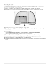
...). 1 Route a 3.31 mm² (12 AWG) copper wire to a water ground location and to the radar pedestal. 2 Connect the wire to the ground connector on the pedestal ( ) using the pre-installed crimp connector. 3 Coat the ground screw and crimp connector with marine sealant. 4 Connect the other end of the wire to the water ground location on the...
...). 1 Route a 3.31 mm² (12 AWG) copper wire to a water ground location and to the radar pedestal. 2 Connect the wire to the ground connector on the pedestal ( ) using the pre-installed crimp connector. 3 Coat the ground screw and crimp connector with marine sealant. 4 Connect the other end of the wire to the water ground location on the...
Installation Instructions
Page 13
... chartplotter's owner's manual for each open-array radar installed on the radar and all of Garmin network cable connectors that has smaller connectors on both ends. • The larger network connectors are available from your Garmin dealer, or go to change, select Options > Radar Setup > Installation > Antenna Configuration > Antenna Size, and select the antenna size. If you must be used on various...
... chartplotter's owner's manual for each open-array radar installed on the radar and all of Garmin network cable connectors that has smaller connectors on both ends. • The larger network connectors are available from your Garmin dealer, or go to change, select Options > Radar Setup > Installation > Antenna Configuration > Antenna Size, and select the antenna size. If you must be used on various...
Installation Instructions
Page 14
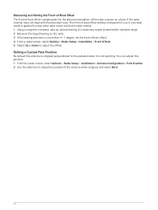
... this position. 1 From the radar screen, select Options > Radar Setup > Installation > Antenna Configuration > Park Position. 2 Use the slider bar to the pedestal when it is not spinning. Measuring and Setting the Front-of-Boat Offset The front-of-boat offset compensates for use in one radar mode is applied to every other radar mode and to the radar overlay. 1 Using a magnetic compass, take an...
... this position. 1 From the radar screen, select Options > Radar Setup > Installation > Antenna Configuration > Park Position. 2 Use the slider bar to the pedestal when it is not spinning. Measuring and Setting the Front-of-Boat Offset The front-of-boat offset compensates for use in one radar mode is applied to every other radar mode and to the radar overlay. 1 Using a magnetic compass, take an...
Installation Instructions
Page 15
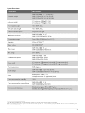
....garmin.com/waterrating. 15 For more information, go to 131°F) 95% at 35°C (95°F) IEC 60529 IPX62 GMR 430 xHD3: 72 nm GMR 1230/2530 xHD3: 96 nm 20 m (66 ft.) GMR 430 xHD3: 4 KW GMR 1230 xHD3: 12 KW GMR 2530 xHD3: 25 KW 4 ft. GMR 2530 xHD3: 24.9 kg (54.9 lb.) 4 ft. Specifications Specification Pedestal weight Antenna weight Power cable length Network cable...
....garmin.com/waterrating. 15 For more information, go to 131°F) 95% at 35°C (95°F) IEC 60529 IPX62 GMR 430 xHD3: 72 nm GMR 1230/2530 xHD3: 96 nm 20 m (66 ft.) GMR 430 xHD3: 4 KW GMR 1230 xHD3: 12 KW GMR 2530 xHD3: 25 KW 4 ft. GMR 2530 xHD3: 24.9 kg (54.9 lb.) 4 ft. Specifications Specification Pedestal weight Antenna weight Power cable length Network cable...

Installation Instructions
Page 16
....) GMR 2536 xHD3 0.17 m (6.69 in.) 0.23 m (9.06 in.) 0.52 m (20.47 in a position on the vessel that is transmitting, the radar should be expected. These minimum safe distances apply for a transmitting radar with a rotating antenna, and are much larger when the antenna is obstructed for any reason, the transmitter will automatically turn off. Antenna Specifications Specification...
....) GMR 2536 xHD3 0.17 m (6.69 in.) 0.23 m (9.06 in.) 0.52 m (20.47 in a position on the vessel that is transmitting, the radar should be expected. These minimum safe distances apply for a transmitting radar with a rotating antenna, and are much larger when the antenna is obstructed for any reason, the transmitter will automatically turn off. Antenna Specifications Specification...

Installation Instructions
Page 17
Center of rotation to the front of rotation to the outer front mounting holes. 17 Center of the pedestal. Dimensions Item Measurement 181.8 mm (7 3/16 in.) 236.2 mm (9 5/16 in.) 25 mm (1 in.) 125 mm (4 15/16 in.) 50 mm (1 15/16 in.) 150 mm (5 29/32 in.) 140 mm (5 1/2 in.) 200 mm (7 7/8 in.) Description Center of rotation to the rear of rotation to the inner front mounting holes. Center of the pedestal. Center of rotation to the outer rear mounting holes. Center of rotation to the inner rear mounting holes.
Center of rotation to the front of rotation to the outer front mounting holes. 17 Center of the pedestal. Dimensions Item Measurement 181.8 mm (7 3/16 in.) 236.2 mm (9 5/16 in.) 25 mm (1 in.) 125 mm (4 15/16 in.) 50 mm (1 15/16 in.) 150 mm (5 29/32 in.) 140 mm (5 1/2 in.) 200 mm (7 7/8 in.) Description Center of rotation to the rear of rotation to the inner front mounting holes. Center of the pedestal. Center of rotation to the outer rear mounting holes. Center of rotation to the inner rear mounting holes.
Installation Instructions
Page 18
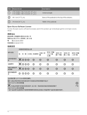
.../T11364 GB/T26572 GB/T26572 产品 18 Item Measurement 4 ft. models: 132.7 cm (4 ft. 4 1/4 in .) Description Antenna length. Open-Source Software License To view the open-source software license(s) used in this product, go to the top of the pedestal. models: 193.7 cm (6 ft. 4 1/4 in.) 45.1 cm (17 3/4 in.) 31.8 cm (12...
.../T11364 GB/T26572 GB/T26572 产品 18 Item Measurement 4 ft. models: 132.7 cm (4 ft. 4 1/4 in .) Description Antenna length. Open-Source Software License To view the open-source software license(s) used in this product, go to the top of the pedestal. models: 193.7 cm (6 ft. 4 1/4 in.) 45.1 cm (17 3/4 in.) 31.8 cm (12...
Installation Instructions
Page 19
... of these instructions to the battery. Flashing red The radar has encountered an error. M/N: AB4560 / AA4560 / A04560 IC: 1792A-B4560 / 1792A-A4560 / 1792A-04560 19 Check all connections. • The inline fuse may not be powering on . Contacting Garmin Support • Go to flashing green. or its subsidiaries Garmin® and the Garmin logo are registered trademarks of Garmin. GMR™ is...
... of these instructions to the battery. Flashing red The radar has encountered an error. M/N: AB4560 / AA4560 / A04560 IC: 1792A-B4560 / 1792A-A4560 / 1792A-04560 19 Check all connections. • The inline fuse may not be powering on . Contacting Garmin Support • Go to flashing green. or its subsidiaries Garmin® and the Garmin logo are registered trademarks of Garmin. GMR™ is...


