
Flush Mount Template
Page 1
... Page Size that is larger than the template ➍. Notice Garmin is not responsible for any damages or expenses resulting from a miscut mounting surface arising from a failure to follow these instructions for Page Scaling ➊. 3 Ensure the check mark is...instructions, may result in the product box. Use the template that came in an incorrectly sized template and therefore an incorrect cutout (too large or too small) on your boat. 1 Select File > Print. ➎ ➌ ➍ ➊ ➋ 2 Select None for printing a mounting template precisely. Printing a Mounting...
... Page Size that is larger than the template ➍. Notice Garmin is not responsible for any damages or expenses resulting from a miscut mounting surface arising from a failure to follow these instructions for Page Scaling ➊. 3 Ensure the check mark is...instructions, may result in the product box. Use the template that came in an incorrectly sized template and therefore an incorrect cutout (too large or too small) on your boat. 1 Select File > Print. ➎ ➌ ➍ ➊ ➋ 2 Select None for printing a mounting template precisely. Printing a Mounting...

Flush Mount Template
Page 2
GMR® 400/600/1200/2500 Series Mounting Template 180° forskydning 180°-forskyvning 180° förskjutning Décalage = 0° Scostamento 0° Versatz von 0° Variación de 0° 180° .... (200 mm) Printed in . (140 mm) Décalage = 180° Scostamento 180° Versatz von 180° Variación de 180° © 2009-15 Garmin Ltd.
GMR® 400/600/1200/2500 Series Mounting Template 180° forskydning 180°-forskyvning 180° förskjutning Décalage = 0° Scostamento 0° Versatz von 0° Variación de 0° 180° .... (200 mm) Printed in . (140 mm) Décalage = 180° Scostamento 180° Versatz von 180° Variación de 180° © 2009-15 Garmin Ltd.

Important Safety and Product Information
Page 2
.... Garmin will be used with the instructions. Marine Warranty Policy: Certain Garmin Marine products in -country distributor and this device must accept any interference, including interference that may not cause interference, and (2) this device under our Limited Warranty are intended to be prepared to human readable form the Software or any part thereof or create any user-serviceable parts. You...
.... Garmin will be used with the instructions. Marine Warranty Policy: Certain Garmin Marine products in -country distributor and this device must accept any interference, including interference that may not cause interference, and (2) this device under our Limited Warranty are intended to be prepared to human readable form the Software or any part thereof or create any user-serviceable parts. You...
Installation Instructions
Page 1
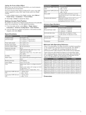
... to support the device's weight. Any damage resulting from Single Side Band (SSB) radios. Software Update You must update the Garmin chartplotter software when you install this radar conforms to the requirements of injury or product damage caused by fire or overheating, the appropriate fuse must be mounted in the product specifications. For instructions on updating the software, see your chartplotter owner's manual...
... to support the device's weight. Any damage resulting from Single Side Band (SSB) radios. Software Update You must update the Garmin chartplotter software when you install this radar conforms to the requirements of injury or product damage caused by fire or overheating, the appropriate fuse must be mounted in the product specifications. For instructions on updating the software, see your chartplotter owner's manual...
Installation Instructions
Page 2
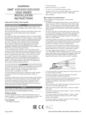
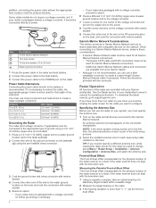
...mounting surface so they no longer turn easily. 2 Align the waveguide on the pedestal with the socket on the bottom of the antenna , and slide the antenna onto the pedestal. Installation Procedures Preparing the Surface and the Radar for the cables using a 32 mm (11/4 in.) drill bit, and route the cables through the surface (optional) (Wiring...receive an accurate radar reading (Front-of the pedestal you need to run the power and network cables through the mounting surface, select a location under the mounting surface, place the shoulder washers on the threaded rods and feed them into the ...
...mounting surface so they no longer turn easily. 2 Align the waveguide on the pedestal with the socket on the bottom of the antenna , and slide the antenna onto the pedestal. Installation Procedures Preparing the Surface and the Radar for the cables using a 32 mm (11/4 in.) drill bit, and route the cables through the surface (optional) (Wiring...receive an accurate radar reading (Front-of the pedestal you need to run the power and network cables through the mounting surface, select a location under the mounting surface, place the shoulder washers on the threaded rods and feed them into the ...
Installation Instructions
Page 3
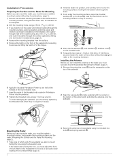
... seal. Item Description To the Garmin Marine Network 10 A fuse holder Red (+) Black (-) To the boat battery (10 to 32 Vdc) 30 A fuse holder Water ground connection 1 Route the power cable to the radar and the voltage converter. 2 Use crimp connectors and heat-shrink tubing to connect the power cable to Power WARNING When connecting the power cable, do not remove the in...
... seal. Item Description To the Garmin Marine Network 10 A fuse holder Red (+) Black (-) To the boat battery (10 to 32 Vdc) 30 A fuse holder Water ground connection 1 Route the power cable to the radar and the voltage converter. 2 Use crimp connectors and heat-shrink tubing to connect the power cable to Power WARNING When connecting the power cable, do not remove the in...
Installation Instructions
Page 4
.... You must be used for each open-array radar installed on your Garmin dealer. • Although it is part of the initial setup process. 2 Select the installed antenna size for Garmin Marine Network connections. ◦ Additional Garmin Marine Network cables and connectors are controlled with the bow-stern axis. 1 Using a magnetic compass, take an optical bearing of wire must use the radar on the...
.... You must be used for each open-array radar installed on your Garmin dealer. • Although it is part of the initial setup process. 2 Select the installed antenna size for Garmin Marine Network connections. ◦ Additional Garmin Marine Network cables and connectors are controlled with the bow-stern axis. 1 Using a magnetic compass, take an optical bearing of wire must use the radar on the...
Installation Instructions
Page 5
... in.) GMR 2526 xHD2 0.17 m (6.69 in.) 0.23 m (9.06 in.) 0.52 m (20.47 in .) Antenna Specifications Specification Measurement Type End-fed slotted waveguide Horizontal beam width 4 ft. These minimum safe distances apply for your radar model on the vessel that is at least this position. 1 From the radar screen, select Menu > Radar Setup > Installation > Antenna Configuration > Park Position. 2 Use the...
... in.) GMR 2526 xHD2 0.17 m (6.69 in.) 0.23 m (9.06 in.) 0.52 m (20.47 in .) Antenna Specifications Specification Measurement Type End-fed slotted waveguide Horizontal beam width 4 ft. These minimum safe distances apply for your radar model on the vessel that is at least this position. 1 From the radar screen, select Menu > Radar Setup > Installation > Antenna Configuration > Park Position. 2 Use the...
Installation Instructions
Page 6
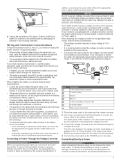
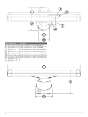
Center of rotation to the outer front mounting holes. 6 Center of rotation to the inner front mounting holes. Item Measurement Description 181.8 mm (7 3/16 in.) Center of rotation to the rear of the pedestal. 236.2 mm (9 5/16 in.) Center of rotation to the front of the pedestal. 25 mm (1 in.) Center of rotation to the inner rear mounting holes. 125 mm (4 15/16 in.) 50 mm (1 15/16 in.) 150 mm (5 29/32 in.) 140 mm (5 1/2 in.) 200 mm (7 7/8 in.) Center of rotation to the outer rear mounting holes.
Center of rotation to the outer front mounting holes. 6 Center of rotation to the inner front mounting holes. Item Measurement Description 181.8 mm (7 3/16 in.) Center of rotation to the rear of the pedestal. 236.2 mm (9 5/16 in.) Center of rotation to the front of the pedestal. 25 mm (1 in.) Center of rotation to the inner rear mounting holes. 125 mm (4 15/16 in.) 50 mm (1 15/16 in.) 150 mm (5 29/32 in.) 140 mm (5 1/2 in.) 200 mm (7 7/8 in.) Center of rotation to the outer rear mounting holes.
Installation Instructions
Page 7
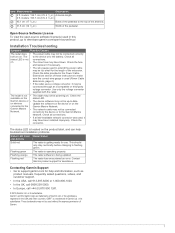
... updated. or its subsidiaries, registered in this product, go to support.garmin.com for help troubleshoot installation problems. Status LED Color Radar Status and Activity Solid red The radar is not connections. models: 132.7 cm (4 ft. 4 1/4 in .) Base of the pedestal to the Garmin Marine Network. Installation Troubleshooting Symptom Possible Causes The radar does • The power cable may have been installed improperly. on . Garmin...
... updated. or its subsidiaries, registered in this product, go to support.garmin.com for help troubleshoot installation problems. Status LED Color Radar Status and Activity Solid red The radar is not connections. models: 132.7 cm (4 ft. 4 1/4 in .) Base of the pedestal to the Garmin Marine Network. Installation Troubleshooting Symptom Possible Causes The radar does • The power cable may have been installed improperly. on . Garmin...


