Installation Manual
Page 8
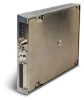
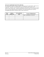
... of this manual (see date on the Garmin Dealer Resource web site at the time of publication of the modification. GDL 69/69A HARDWARE MOD LEVEL HISTORY The following table identifies hardware modification (Mod) Levels for the GDL 69/69A. Mod Levels are encouraged to access the most... up-to-date bulletin and advisory information on front cover) and is current at www.garmin.com using their Garmin-provided user...
... of this manual (see date on the Garmin Dealer Resource web site at the time of publication of the modification. GDL 69/69A HARDWARE MOD LEVEL HISTORY The following table identifies hardware modification (Mod) Levels for the GDL 69/69A. Mod Levels are encouraged to access the most... up-to-date bulletin and advisory information on front cover) and is current at www.garmin.com using their Garmin-provided user...

Installation Manual
Page 9
... to a Garmin audio panel for amplification and distribution of airframes under an appropriate TC or STC. General Description 1 GENERAL DESCRIPTION 1.1 Scope The information in this manual is used to interface to the GDL 69/69A. For display of weather information and control of 400/500 series units). The GDL 69A is also interfaced to the GDL 69/69A. GDL 69/69A Installation Manual...
... to a Garmin audio panel for amplification and distribution of airframes under an appropriate TC or STC. General Description 1 GENERAL DESCRIPTION 1.1 Scope The information in this manual is used to interface to the GDL 69/69A. For display of weather information and control of 400/500 series units). The GDL 69A is also interfaced to the GDL 69/69A. GDL 69/69A Installation Manual...
Installation Manual
Page 10
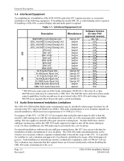
...Garmin Garmin Garmin Garmin Garmin Garmin Garmin Garmin Garmin Garmin Garmin Garmin AT Garmin AT Garmin AT Garmin AT Garmin AT Garmin Garmin Software Version (Or later FAA approved version) Ver. 5.5 4.01 5.00 5.00 4.04 4.04 4.04 4.04 4.04 5.04 5.04 5.04 N/A N/A N/A N/A N/A N/A N/A O R * 400/500 series units must use Pilot Guide Addendum 190-00140-13 Revision D, or later. 400/500 series units may be provided to the crew locations. The GDL 69A...satisfactorily without disabling the GDL 69A audio entertainment to the crew. Page 1-2 Revision E GDL 69/69A Installation Manual 190-00355-...
...Garmin Garmin Garmin Garmin Garmin Garmin Garmin Garmin Garmin Garmin Garmin Garmin AT Garmin AT Garmin AT Garmin AT Garmin AT Garmin Garmin Software Version (Or later FAA approved version) Ver. 5.5 4.01 5.00 5.00 4.04 4.04 4.04 4.04 4.04 5.04 5.04 5.04 N/A N/A N/A N/A N/A N/A N/A O R * 400/500 series units must use Pilot Guide Addendum 190-00140-13 Revision D, or later. 400/500 series units may be provided to the crew locations. The GDL 69A...satisfactorily without disabling the GDL 69A audio entertainment to the crew. Page 1-2 Revision E GDL 69/69A Installation Manual 190-00355-...
Installation Manual
Page 11
... activated for activating your unit. Furthermore, the AMBE(R) voice compression software included in this product is an interface summary for the GDL 69/69A units. Note that the GDL 69 does not have the audio interface. • 3 RS-232 Inputs/Outputs • 4 Ethernet Inputs/Outputs • 5 ... Summary The following list is protected by aircraft avionics power bus) GDL 69/69A Installation Manual 190-00355-02 Page 1-3 Revision E XM features digital quality audio. Refer to Section 4.5 for instructions for the first use within this or any other way convert the object code into human...
... activated for activating your unit. Furthermore, the AMBE(R) voice compression software included in this product is an interface summary for the GDL 69/69A units. Note that the GDL 69 does not have the audio interface. • 3 RS-232 Inputs/Outputs • 4 Ethernet Inputs/Outputs • 5 ... Summary The following list is protected by aircraft avionics power bus) GDL 69/69A Installation Manual 190-00355-02 Page 1-3 Revision E XM features digital quality audio. Refer to Section 4.5 for instructions for the first use within this or any other way convert the object code into human...

Installation Manual
Page 15
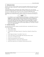
... Garmin Optional Displays GDU 1040 Installation Manual GA 55A, GA 56A and GA 57 Antenna Installation Manual XM™ Satellite Radio Activation Instructions MX20 Installation Manual SL15 Audio Panel Installation Manual SL10 Audio Panel Installation Manual 1.10 Certification The GDL 69 and GDL 69A...GDL 69/69A, the technician should be responsible for two years from defects in materials or workmanship for any components that the customer shall be prepared that is large enough to accommodate sufficient packing material to the customer for parts or labor, provided that fail in normal use...
... Garmin Optional Displays GDU 1040 Installation Manual GA 55A, GA 56A and GA 57 Antenna Installation Manual XM™ Satellite Radio Activation Instructions MX20 Installation Manual SL15 Audio Panel Installation Manual SL10 Audio Panel Installation Manual 1.10 Certification The GDL 69 and GDL 69A...GDL 69/69A, the technician should be responsible for two years from defects in materials or workmanship for any components that the customer shall be prepared that is large enough to accommodate sufficient packing material to the customer for parts or labor, provided that fail in normal use...

Installation Manual
Page 16
... contact your local Garmin Authorized Service Center. Phone: 913/397.8200 FAX: 913/397.0836 Garmin (Europe) Ltd. Phone: 44/1794.519944 FAX: 44/1794.519222 Page 1-8 Revision E GDL 69/69A Installation Manual 190-00355-02 Products sold through an online auction. Garmin will not replace...Industrial Estate Romsey, SO51 9DL, U.K. General Description IN NO EVENT SHALL GARMIN BE LIABLE FOR ANY INCIDENTAL, SPECIAL, INDIRECT OR CONSEQUENTIAL DAMAGES, WHETHER RESULTING FROM THE USE, MISUSE, OR INABILITY TO USE THIS PRODUCT OR FROM DEFECTS IN THE PRODUCT. Online auction confirmations are...
... contact your local Garmin Authorized Service Center. Phone: 913/397.8200 FAX: 913/397.0836 Garmin (Europe) Ltd. Phone: 44/1794.519944 FAX: 44/1794.519222 Page 1-8 Revision E GDL 69/69A Installation Manual 190-00355-02 Products sold through an online auction. Garmin will not replace...Industrial Estate Romsey, SO51 9DL, U.K. General Description IN NO EVENT SHALL GARMIN BE LIABLE FOR ANY INCIDENTAL, SPECIAL, INDIRECT OR CONSEQUENTIAL DAMAGES, WHETHER RESULTING FROM THE USE, MISUSE, OR INABILITY TO USE THIS PRODUCT OR FROM DEFECTS IN THE PRODUCT. Online auction confirmations are...

Installation Manual
Page 18
...rack options available, the remote rack and the modular rack for Remote Rack Page 2-2 Revision E GDL 69/69A Installation Manual 190-00355-02 Suggested Mounting Locations for use with the G1000 system. Installation Procedure 2.3.2 Equipment Required But Not Supplied • Wire: MIL... for selected wire size 2.4 Equipment Mounting 2.4.1 Rack Location and Installation The GDL 69/69A may be mounted in a pressurized or unpressurized location. when mounting, avoid locating the GDL 69/69A near sources that produce high levels of heat. The GDL 69/69A does not require forced-air cooling;
...rack options available, the remote rack and the modular rack for Remote Rack Page 2-2 Revision E GDL 69/69A Installation Manual 190-00355-02 Suggested Mounting Locations for use with the G1000 system. Installation Procedure 2.3.2 Equipment Required But Not Supplied • Wire: MIL... for selected wire size 2.4 Equipment Mounting 2.4.1 Rack Location and Installation The GDL 69/69A may be mounted in a pressurized or unpressurized location. when mounting, avoid locating the GDL 69/69A near sources that produce high levels of heat. The GDL 69/69A does not require forced-air cooling;

Installation Manual
Page 19
... of the G1000 integrated avionics system rack. 2.4.4 Remote Switches Installation of rocker switches vs. Wire used to Appendix C. BACK PLATE ASSEMBLY P/N: 011-00796-35 CONNECTOR KIT ASSEMBLY P/N: 011-00997-00 GDL 69 P/N: 011-00986-00 GDL 69A P/N: 001-00987-00 GDL 69 REMOTE MOUNT RACK P/N: 115-00658-00 Figure 2-2. Each rocker switch installed must be made on...
... of the G1000 integrated avionics system rack. 2.4.4 Remote Switches Installation of rocker switches vs. Wire used to Appendix C. BACK PLATE ASSEMBLY P/N: 011-00796-35 CONNECTOR KIT ASSEMBLY P/N: 011-00997-00 GDL 69 P/N: 011-00986-00 GDL 69A P/N: 001-00987-00 GDL 69 REMOTE MOUNT RACK P/N: 115-00658-00 Figure 2-2. Each rocker switch installed must be made on...

Installation Manual
Page 20
... NUT PLATE KIT 2 115-00657-00 2 PLCS MAY ALTERNATELY USE P/N 115-00511-00 (PART OF KIT 011-01148-00) 3. PART OF 011-00997-00 CONNECTOR KIT 4. APPLY THREAD LOCKING COMPOUND TO ALL THREADED FASTENERS. Modular Rack for the G1000 Page 2-4 Revision E GDL 69/69A Installation Manual 190-00355-02 Installation Procedure Channel Volume Mute...
... NUT PLATE KIT 2 115-00657-00 2 PLCS MAY ALTERNATELY USE P/N 115-00511-00 (PART OF KIT 011-01148-00) 3. PART OF 011-00997-00 CONNECTOR KIT 4. APPLY THREAD LOCKING COMPOUND TO ALL THREADED FASTENERS. Modular Rack for the G1000 Page 2-4 Revision E GDL 69/69A Installation Manual 190-00355-02 Installation Procedure Channel Volume Mute...
Installation Manual
Page 21
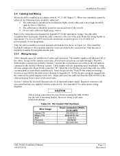
... into the 78-pin D-Sub connector housing location as appropriate. Table 2-2. Then install the backshell connector to the rear plate using the screws provided in Appendix D. Cable lengths will vary depending upon installation. Required connectors and associated hardware are made through ... installer supplies and fabricates all wires going to the interconnection diagrams in Appendix D for errors before inserting the GDL 69/69A into the connector by Garmin. Construct the wiring harness according to the information contained in this and the following issues should be addressed: ...
... into the 78-pin D-Sub connector housing location as appropriate. Table 2-2. Then install the backshell connector to the rear plate using the screws provided in Appendix D. Cable lengths will vary depending upon installation. Required connectors and associated hardware are made through ... installer supplies and fabricates all wires going to the interconnection diagrams in Appendix D for errors before inserting the GDL 69/69A into the connector by Garmin. Construct the wiring harness according to the information contained in this and the following issues should be addressed: ...

Installation Manual
Page 24
Refer to easily terminate shield grounds at the backshell housing using screws (8). Crimp pins (4) onto each wire prior to crimping. 2. Page 2-8 Revision E Figure 2-6. Backshell Assembly GDL 69/69A Installation Manual 190-00355-02 Installation Procedure 2.5.3 Configuration Module Installation The GDL 69/69A connector kit includes one Garmin backshell assembly. Strip 1/8" of insulation from each wire of the spacer. 4. Insert...
Refer to easily terminate shield grounds at the backshell housing using screws (8). Crimp pins (4) onto each wire prior to crimping. 2. Page 2-8 Revision E Figure 2-6. Backshell Assembly GDL 69/69A Installation Manual 190-00355-02 Installation Procedure 2.5.3 Configuration Module Installation The GDL 69/69A connector kit includes one Garmin backshell assembly. Strip 1/8" of insulation from each wire of the spacer. 4. Insert...

Installation Manual
Page 33
Unit Weights Item GDL 69 Weight GDL 69 and Remote Rack Weight GDL 69 and Modular Rack Weight GDL 69A Weight GDL 69A and Remote Rack Weight GDL 69A and Modular Rack Weight GA 55 Antenna GA 55A Antenna GA 57 Antenna Weight 1.72 lbs (0.78 kg) 2.69 lbs (1.22 kg) 2.67 lbs (1.21 kg) 1.86 lbs (0.84 kg) ... (0.20 kg) 0.47 lbs (0.21 kg) 2.8 Electrical Load Analysis An electrical load analysis should be completed on FAA Form 337. Use the following values for computation: GDL 69 Unit Status Off On GDL 69A Max Current @ 28 VDC 0.01 A 0.28 A Max Current @ 14 VDC 0.01 A 0.425 A Unit Status Off On...
Unit Weights Item GDL 69 Weight GDL 69 and Remote Rack Weight GDL 69 and Modular Rack Weight GDL 69A Weight GDL 69A and Remote Rack Weight GDL 69A and Modular Rack Weight GA 55 Antenna GA 55A Antenna GA 57 Antenna Weight 1.72 lbs (0.78 kg) 2.69 lbs (1.22 kg) 2.67 lbs (1.21 kg) 1.86 lbs (0.84 kg) ... (0.20 kg) 0.47 lbs (0.21 kg) 2.8 Electrical Load Analysis An electrical load analysis should be completed on FAA Form 337. Use the following values for computation: GDL 69 Unit Status Off On GDL 69A Max Current @ 28 VDC 0.01 A 0.28 A Max Current @ 14 VDC 0.01 A 0.425 A Unit Status Off On...

Installation Manual
Page 37
... 3-1. System Interconnects 3 SYSTEM INTERCONNECTS 3.1 Pin Out List View of P691 connector looking at rear of unit. 60 61 62 63 64 65 66 67 68 69 70 71 72 73 74 75 76 77 78 40 41 42 43 44 45 46 47 48 49 50 51 52 53 54 55... 3 A Ethernet Out 3 B Ethernet Out 3 A Spare Aircraft Power 1 I/O Notes Out Out Out -In In In For Factory Use Only Out For Factory Use Only In In ------Out GDL 69A Only Out GDL 69A Only Out GDL 69A Only -Out In In Out Out In In Out Out In In Out Out -- In GDL 69/69A Installation Manual 190-00355-02 Page 3-1 Revision E
... 3-1. System Interconnects 3 SYSTEM INTERCONNECTS 3.1 Pin Out List View of P691 connector looking at rear of unit. 60 61 62 63 64 65 66 67 68 69 70 71 72 73 74 75 76 77 78 40 41 42 43 44 45 46 47 48 49 50 51 52 53 54 55... 3 A Ethernet Out 3 B Ethernet Out 3 A Spare Aircraft Power 1 I/O Notes Out Out Out -In In In For Factory Use Only Out For Factory Use Only In In ------Out GDL 69A Only Out GDL 69A Only Out GDL 69A Only -Out In In Out Out In In Out Out In In Out Out -- In GDL 69/69A Installation Manual 190-00355-02 Page 3-1 Revision E

Installation Manual
Page 38
GDL 69A Only -- GDL 69A Only In In In For factory use only In In In In In --In In Note 1: Line Out Audio is not supported in GDL 69A with software version prior to 3.00. GDL 69A Only -- GDL 69A Only -- System Interconnects Pin # 36 37 38 39 40 41 42 43... Down (-) Volume Up (+) Volume Down (-) Signal Ground Spare Data Link Remote Power Off Power Ground I/O Notes -In --I/O -----------Out GDL 69A Only (Note 1) Out GDL 69A Only (Note 1) Out GDL 69A Only (Note 1) -In In Out Out Out -- Page 3-2 Revision E GDL 69/69A Installation Manual 190-00355-02 GDL 69A Only -- GDL 69A Only --
GDL 69A Only -- GDL 69A Only In In In For factory use only In In In In In --In In Note 1: Line Out Audio is not supported in GDL 69A with software version prior to 3.00. GDL 69A Only -- GDL 69A Only -- System Interconnects Pin # 36 37 38 39 40 41 42 43... Down (-) Volume Up (+) Volume Down (-) Signal Ground Spare Data Link Remote Power Off Power Ground I/O Notes -In --I/O -----------Out GDL 69A Only (Note 1) Out GDL 69A Only (Note 1) Out GDL 69A Only (Note 1) -In In Out Out Out -- Page 3-2 Revision E GDL 69/69A Installation Manual 190-00355-02 GDL 69A Only -- GDL 69A Only --

Installation Manual
Page 41
...Mute discrete provides audio volume control of the audio output. (Note: The volume and mute controls have no affect on use . This is left channel audio GDL 69/69A Installation Manual 190-00355-02 Page 3-5 Revision E Each input presents a load of these inputs are active low (i.e. P691...-67 Discrete 2 P691-68 Discrete 1 P691-69 Test Enable 3.2.6 Remote Power ON/OFF Input The unit will go active with input voltages above 3 volts. System Interconnects 3.2.5 Discrete Inputs (GDL 69A Only) The discrete inputs are used ) The following discrete input pins are reserved for the...
...Mute discrete provides audio volume control of the audio output. (Note: The volume and mute controls have no affect on use . This is left channel audio GDL 69/69A Installation Manual 190-00355-02 Page 3-5 Revision E Each input presents a load of these inputs are active low (i.e. P691...-67 Discrete 2 P691-68 Discrete 1 P691-69 Test Enable 3.2.6 Remote Power ON/OFF Input The unit will go active with input voltages above 3 volts. System Interconnects 3.2.5 Discrete Inputs (GDL 69A Only) The discrete inputs are used ) The following discrete input pins are reserved for the...

Installation Manual
Page 42
... P691-50 P691-51 P691-55 P691-76 Page 3-6 Revision E GDL 69/69A Installation Manual 190-00355-02 This is always at a fixed output. Use of these pins as they may result in future configurations of the GDL 69/69A. Support for the Line Out audio output P691-53 Line Out Right...to these pins may be connected. Wires should not be used in unintended behavior. This is the left channel audio 3.2.9 Reserved Pins These pins are spare pins and not connected inside the GDL 69/69A. System Interconnects 3.2.8 Line Out (GDL 69A Only) The Line Out output is the right channel audio...
... P691-50 P691-51 P691-55 P691-76 Page 3-6 Revision E GDL 69/69A Installation Manual 190-00355-02 This is always at a fixed output. Use of these pins as they may result in future configurations of the GDL 69/69A. Support for the Line Out audio output P691-53 Line Out Right...to these pins may be connected. Wires should not be used in unintended behavior. This is the left channel audio 3.2.9 Reserved Pins These pins are spare pins and not connected inside the GDL 69/69A. System Interconnects 3.2.8 Line Out (GDL 69A Only) The Line Out output is the right channel audio...

Installation Manual
Page 47
... signals will mute audio output from the GDL 69A. More optional checkout procedures are available after the GDL 69/69A is activated with the 400/500 series, the GDL 69A audio feature is not operational. Volume Up/Down- With installations where the Audio Suppression is used . The gear warning horn may be used , activate the Stall Warning, Gear Warning...
... signals will mute audio output from the GDL 69A. More optional checkout procedures are available after the GDL 69/69A is activated with the 400/500 series, the GDL 69A audio feature is not operational. Volume Up/Down- With installations where the Audio Suppression is used . The gear warning horn may be used , activate the Stall Warning, Gear Warning...

Installation Manual
Page 51
... or alerts, such as such, if an option to power the unit from a non-essential bus. 6.2.1 Antenna The GDL 69/69A is compatible with the Garmin antennas listed in Table 1-5 or those shown in accordance with equivalent specifications. In both cases, each pilot station must be...and approval of the field approval process. The GDL 69A audio entertainment may be used. For aircraft installations with non-electric stall/gear warning horns, this manual and may require further evaluation and/or certification approval. The GDL 69/69A is the installer's responsibility to crew locations ...
... or alerts, such as such, if an option to power the unit from a non-essential bus. 6.2.1 Antenna The GDL 69/69A is compatible with the Garmin antennas listed in Table 1-5 or those shown in accordance with equivalent specifications. In both cases, each pilot station must be...and approval of the field approval process. The GDL 69A audio entertainment may be used. For aircraft installations with non-electric stall/gear warning horns, this manual and may require further evaluation and/or certification approval. The GDL 69/69A is the installer's responsibility to crew locations ...
Installation Manual
Page 55
...following installation instructions and limitations described in this GDL 69/69A Installation Manual. A.2 Permission to use STC Consistent with Order 8110.4C and AC 21-40, Garmin AT grants permission to Garmin dealers, installers and owners of the GDL 69 and GDL 69A to use STC SA01487SE and the data associated with ...Approved Model List (AML), Master Data List (Garmin P/N 005-C0217-00) information is attached to ...
...following installation instructions and limitations described in this GDL 69/69A Installation Manual. A.2 Permission to use STC Consistent with Order 8110.4C and AC 21-40, Garmin AT grants permission to Garmin dealers, installers and owners of the GDL 69 and GDL 69A to use STC SA01487SE and the data associated with ...Approved Model List (AML), Master Data List (Garmin P/N 005-C0217-00) information is attached to ...

Installation Manual
Page 59
... combined weight of equipment mounting structures, such as shelves, mounting plates and mounting brackets, used , such as lock nuts and lock washers. 3. Static Test Load (GDL 69A with the methods outlined in AC43.13-2A Chapter 1 to mount the GDL 69/69A remote rack. After the structure is 2.83 lbs, the static loads which will be...
... combined weight of equipment mounting structures, such as shelves, mounting plates and mounting brackets, used , such as lock nuts and lock washers. 3. Static Test Load (GDL 69A with the methods outlined in AC43.13-2A Chapter 1 to mount the GDL 69/69A remote rack. After the structure is 2.83 lbs, the static loads which will be...


