Installation Manual
Page 3
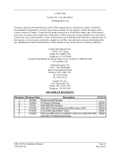
...06 Remove XM antenna installation data and added GA 55A and GA 57 antenna references. Garmin hereby grants permission to download a single copy of this manual and of any revision to this manual onto a hard drive or other electronic storage medium to be reproduced, copied, transmitted...copy of this manual or of any revision hereto, provided that such electronic or printed copy of this manual or revision must contain the complete text of this manual or any unauthorized commercial distribution of Garmin. ECO # -----28645 29512 32449 33407 38688 GDL 69/69A Installation Manual 190-00355-02...
...06 Remove XM antenna installation data and added GA 55A and GA 57 antenna references. Garmin hereby grants permission to download a single copy of this manual and of any revision to this manual onto a hard drive or other electronic storage medium to be reproduced, copied, transmitted...copy of this manual or of any revision hereto, provided that such electronic or printed copy of this manual or revision must contain the complete text of this manual or any unauthorized commercial distribution of Garmin. ECO # -----28645 29512 32449 33407 38688 GDL 69/69A Installation Manual 190-00355-02...

Installation Manual
Page 4
..., Chapter VII, Subchapter C) and which may be exported, released, or disclosed to cause cancer, birth defects, or reproductive harm. Visit the Garmin web site (www.garmin.com) for software version 2.11, 2.13, 2.14, 3.00, 3.01, 3.02 or later. A violation of the EAR may not ...its components contain chemicals known to our web site at www.garmin.com/prop65. Page iv Revision E GDL 69/69A Installation Manual 190-00355-02 If you have any reproduced portion of this and other Garmin products. This manual is written for current updates and supplemental information concerning the ...
..., Chapter VII, Subchapter C) and which may be exported, released, or disclosed to cause cancer, birth defects, or reproductive harm. Visit the Garmin web site (www.garmin.com) for software version 2.11, 2.13, 2.14, 3.00, 3.01, 3.02 or later. A violation of the EAR may not ...its components contain chemicals known to our web site at www.garmin.com/prop65. Page iv Revision E GDL 69/69A Installation Manual 190-00355-02 If you have any reproduced portion of this and other Garmin products. This manual is written for current updates and supplemental information concerning the ...

Installation Manual
Page 5
... 4-3 4.5 Activation with XM Satellite Radio 4-5 5 TROUBLESHOOTING...5-1 6 LIMITATIONS ...6-1 6.1 Operation ...6-1 6.2 Installation ...6-1 7 PERIODIC MAINTENANCE ...7-1 7.1 Audio Suppression...7-1 7.2 Equipment Calibration...7-1 7.3 Cleaning ...7-1 APPENDIX A - CONSTRUCTION AND VALIDATION OF STRUCTURES C-1 APPENDIX D - INSTALLATION DRAWINGS D-1 GDL 69/69A Installation Manual 190-00355-02 Page v Revision E
... 4-3 4.5 Activation with XM Satellite Radio 4-5 5 TROUBLESHOOTING...5-1 6 LIMITATIONS ...6-1 6.1 Operation ...6-1 6.2 Installation ...6-1 7 PERIODIC MAINTENANCE ...7-1 7.1 Audio Suppression...7-1 7.2 Equipment Calibration...7-1 7.3 Cleaning ...7-1 APPENDIX A - CONSTRUCTION AND VALIDATION OF STRUCTURES C-1 APPENDIX D - INSTALLATION DRAWINGS D-1 GDL 69/69A Installation Manual 190-00355-02 Page v Revision E

Installation Manual
Page 6
.... GDL 69/69A Installation 2-19 Figure 3-1. GDL 69 Interconnect to Warning Horns D-7 Figure D-6. Interconnect to MFD and 400/500 Series D-6 Figure D-5. GDL 69 Interconnect to GDU 104x D-4 Figure D-3. Garmin Connector Assembly 2-7 Figure 2-6. Data Link Configuration Page on the 400/500 Series 4-4 Figure 4-3. Data Link Configuration Page on the MX20 4-3 Figure 4-2. Optional Audio Attenuation D-8 Page vi Revision E GDL 69/69A Installation Manual 190...
.... GDL 69/69A Installation 2-19 Figure 3-1. GDL 69 Interconnect to Warning Horns D-7 Figure D-6. Interconnect to MFD and 400/500 Series D-6 Figure D-5. GDL 69 Interconnect to GDU 104x D-4 Figure D-3. Garmin Connector Assembly 2-7 Figure 2-6. Data Link Configuration Page on the 400/500 Series 4-4 Figure 4-3. Data Link Configuration Page on the MX20 4-3 Figure 4-2. Optional Audio Attenuation D-8 Page vi Revision E GDL 69/69A Installation Manual 190...
Installation Manual
Page 8
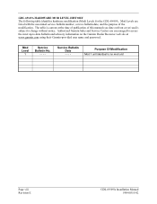
... purpose of this manual (see date on front cover) and is current at the time of publication of the modification. The table is subject to -date bulletin and advisory information on the Garmin Dealer Resource web site at www.garmin.com using their Garmin-provided user name and password. Service Bulletin Date - - - - GDL 69/69A HARDWARE MOD...
... purpose of this manual (see date on front cover) and is current at the time of publication of the modification. The table is subject to -date bulletin and advisory information on the Garmin Dealer Resource web site at www.garmin.com using their Garmin-provided user name and password. Service Bulletin Date - - - - GDL 69/69A HARDWARE MOD...

Installation Manual
Page 9
... airframe installation may be controlled with the addition of the audio signal. GDL 69/69A Unit View 1.3 Equipment Description The GDL 69/69A is a weather data receiver. Other equipment may be required if equipment not covered in this manual are within may also be interfaced to a Garmin audio panel for additional information. Figure 1-1. Only the equipment interfaces covered...
... airframe installation may be controlled with the addition of the audio signal. GDL 69/69A Unit View 1.3 Equipment Description The GDL 69/69A is a weather data receiver. Other equipment may be required if equipment not covered in this manual are within may also be interfaced to a Garmin audio panel for additional information. Figure 1-1. Only the equipment interfaces covered...
Installation Manual
Page 10
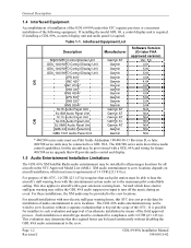
...Panel Unit SL10S Audio Panel Unit SL10MS Audio Panel Unit GMA 340 Audio Panel Unit GMA 1347 Audio Panel Unit Manufacturer Garmin AT Garmin Garmin Garmin Garmin Garmin Garmin Garmin Garmin Garmin Garmin Garmin Garmin AT Garmin AT Garmin AT Garmin AT Garmin AT Garmin Garmin Software Version (Or later FAA approved version) Ver. 5.5 4.01 5.00 5.00 4.04 4.04 4.04 4.04... each pilot station must meet requirements of 14 CFR §23.1431(e). Page 1-2 Revision E GDL 69/69A Installation Manual 190-00355-02 For aircraft installations with non-electric stall/gear warning horns, this STC, 14 CFR...
...Panel Unit SL10S Audio Panel Unit SL10MS Audio Panel Unit GMA 340 Audio Panel Unit GMA 1347 Audio Panel Unit Manufacturer Garmin AT Garmin Garmin Garmin Garmin Garmin Garmin Garmin Garmin Garmin Garmin Garmin Garmin AT Garmin AT Garmin AT Garmin AT Garmin AT Garmin Garmin Software Version (Or later FAA approved version) Ver. 5.5 4.01 5.00 5.00 4.04 4.04 4.04 4.04... each pilot station must meet requirements of 14 CFR §23.1431(e). Page 1-2 Revision E GDL 69/69A Installation Manual 190-00355-02 For aircraft installations with non-electric stall/gear warning horns, this STC, 14 CFR...
Installation Manual
Page 11
..., reverse engineer, or disassemble the object code, or in any other software contained in an XM Satellite Radio is protected by aircraft avionics power bus) GDL 69/69A Installation Manual 190-00355-02 Page 1-3 Revision E America's most popular satellite radio service gives you the power to choose what you want to -coast coverage. Subscriptions...
..., reverse engineer, or disassemble the object code, or in any other software contained in an XM Satellite Radio is protected by aircraft avionics power bus) GDL 69/69A Installation Manual 190-00355-02 Page 1-3 Revision E America's most popular satellite radio service gives you the power to choose what you want to -coast coverage. Subscriptions...

Installation Manual
Page 12
...(18.26 cm) 1.86 lbs (0.84 kg) 2.83 lbs (1.27 kg) NOTE See Table 2-8 outlining weights for the GDL 69, GDL 69A, remote rack, and modular rack. General Description 1.8 Technical Specifications The GDL 69/69A and GA 55/GA55A XM antenna are PMA approved and there is the responsibility of those desiring to install this...within the prescribed standards. For detailed specifications, see the Environmental Qualification form in Appendix B. The GA 57 GPS/WAAS - Table 1-2. Page 1-4 Revision E GDL 69/69A Installation Manual 190-00355-02 XM antenna is TSO authorized under TSO-c144.
...(18.26 cm) 1.86 lbs (0.84 kg) 2.83 lbs (1.27 kg) NOTE See Table 2-8 outlining weights for the GDL 69, GDL 69A, remote rack, and modular rack. General Description 1.8 Technical Specifications The GDL 69/69A and GA 55/GA55A XM antenna are PMA approved and there is the responsibility of those desiring to install this...within the prescribed standards. For detailed specifications, see the Environmental Qualification form in Appendix B. The GA 57 GPS/WAAS - Table 1-2. Page 1-4 Revision E GDL 69/69A Installation Manual 190-00355-02 XM antenna is TSO authorized under TSO-c144.

Installation Manual
Page 13
GDL 69/69A Modular Rack Unit Dimensions GDL 69/69A Installation Manual 190-00355-02 Page 1-5 Revision E GDL 69/69A Remote Rack Unit Dimensions 1.23 31.1 WITH DIMPLES 1.20 30.5 WITHOUT DIMPLES 6.90 175.3 TYP 7.26 184.4 6.30 160.0 3.00 76.2 ANTENNA J691 .60 15.2 ....
GDL 69/69A Modular Rack Unit Dimensions GDL 69/69A Installation Manual 190-00355-02 Page 1-5 Revision E GDL 69/69A Remote Rack Unit Dimensions 1.23 31.1 WITH DIMPLES 1.20 30.5 WITHOUT DIMPLES 6.90 175.3 TYP 7.26 184.4 6.30 160.0 3.00 76.2 ANTENNA J691 .60 15.2 ....
Installation Manual
Page 14
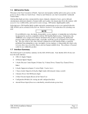
... Description 1.8.1 General Antenna Requirements Garmin recommends the Garmin XM antenna shown in Table 1-6 should work with the certification of equivalent antennas. However, any equivalent XM antenna with specifications listed in the Table 1-5 below. This STC does not support installations of the GDL 69/69A. These antennas are approved with the GDL 69/69A. XM Satellite Radio Antenna Minimum...
... Description 1.8.1 General Antenna Requirements Garmin recommends the Garmin XM antenna shown in Table 1-6 should work with the certification of equivalent antennas. However, any equivalent XM antenna with specifications listed in the Table 1-5 below. This STC does not support installations of the GDL 69/69A. These antennas are approved with the GDL 69/69A. XM Satellite Radio Antenna Minimum...

Installation Manual
Page 15
... the unit to abuse, misuse, accident or unauthorized alteration or repairs. Within this manual. This warranty does not cover failures due to Garmin until the carrier has authorized the claim. GDL 69/69A Installation Manual 190-00355-02 Page 1-7 Revision E Before installing the GDL 69/69A, the technician should be prepared that fail in materials or workmanship for installing...
... the unit to abuse, misuse, accident or unauthorized alteration or repairs. Within this manual. This warranty does not cover failures due to Garmin until the carrier has authorized the claim. GDL 69/69A Installation Manual 190-00355-02 Page 1-7 Revision E Before installing the GDL 69/69A, the technician should be prepared that fail in materials or workmanship for installing...

Installation Manual
Page 16
..., Inc. 1200 East 151st Street Olathe, Kansas 66062, U.S.A. Garmin retains the exclusive right to you , call Garmin Customer Service at its sole discretion. To obtain warranty service, contact your local Garmin Authorized Service Center. Phone: 44/1794.519944 FAX: 44/1794.519222 Page 1-8 Revision E GDL 69/69A Installation Manual 190-00355-02 To obtain warranty service, an...
..., Inc. 1200 East 151st Street Olathe, Kansas 66062, U.S.A. Garmin retains the exclusive right to you , call Garmin Customer Service at its sole discretion. To obtain warranty service, contact your local Garmin Authorized Service Center. Phone: 44/1794.519944 FAX: 44/1794.519222 Page 1-8 Revision E GDL 69/69A Installation Manual 190-00355-02 To obtain warranty service, an...
Installation Manual
Page 17
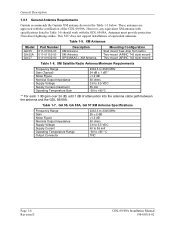
... the necessity for a successful installation. Prior to their installation manuals. For interconnects with the GDU 104x, MX20 MFD or 400/500 series refer to Appendix D of the GDL 69/69A installation as it is covered under separate Garmin GA Antenna AML STC. 2.2 Pre-Installation Information Always follow ...the aircraft TC or STC requirements. Read the entire manual before closing the work area in the following table....
... the necessity for a successful installation. Prior to their installation manuals. For interconnects with the GDU 104x, MX20 MFD or 400/500 series refer to Appendix D of the GDL 69/69A installation as it is covered under separate Garmin GA Antenna AML STC. 2.2 Pre-Installation Information Always follow ...the aircraft TC or STC requirements. Read the entire manual before closing the work area in the following table....

Installation Manual
Page 18
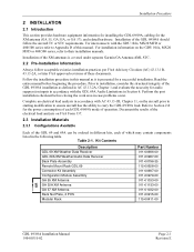
...options available, the remote rack and the modular rack for selected wire size 2.4 Equipment Mounting 2.4.1 Rack Location and Installation The GDL 69/69A may be mounted in a pressurized or unpressurized location. Installation Procedure 2.3.2 Equipment Required But Not Supplied • Wire: MIL-W-22759... Screw (MS24693, AN507R or equivalent) • Circuit Breaker: Appropriate for use with the G1000 system. The GDL 69/69A does not require forced-air cooling; Suggested Mounting Locations for Remote Rack Page 2-2 Revision E GDL 69/69A Installation Manual 190-00355-02 Figure 2-1.
...options available, the remote rack and the modular rack for selected wire size 2.4 Equipment Mounting 2.4.1 Rack Location and Installation The GDL 69/69A may be mounted in a pressurized or unpressurized location. Installation Procedure 2.3.2 Equipment Required But Not Supplied • Wire: MIL-W-22759... Screw (MS24693, AN507R or equivalent) • Circuit Breaker: Appropriate for use with the G1000 system. The GDL 69/69A does not require forced-air cooling; Suggested Mounting Locations for Remote Rack Page 2-2 Revision E GDL 69/69A Installation Manual 190-00355-02 Figure 2-1.

Installation Manual
Page 19
... equivalent.) Ensure that the chosen location is used for the GDL 69/69A remote mount rack dimensions. BACK PLATE ASSEMBLY P/N: 011-00796-35 CONNECTOR KIT ASSEMBLY P/N: 011-00997-00 GDL 69 P/N: 011-00986-00 GDL 69A P/N: 001-00987-00 GDL 69 REMOTE MOUNT RACK P/N: 115-00658-00 Figure 2-2. GDL 69/69A Installation Manual 190-00355-02 Page 2-3 Revision E If it is necessary to...
... equivalent.) Ensure that the chosen location is used for the GDL 69/69A remote mount rack dimensions. BACK PLATE ASSEMBLY P/N: 011-00796-35 CONNECTOR KIT ASSEMBLY P/N: 011-00997-00 GDL 69 P/N: 011-00986-00 GDL 69A P/N: 001-00987-00 GDL 69 REMOTE MOUNT RACK P/N: 115-00658-00 Figure 2-2. GDL 69/69A Installation Manual 190-00355-02 Page 2-3 Revision E If it is necessary to...

Installation Manual
Page 20
...-00185-78 3 125-00059-04 1 211-63234-10 1 3 PLCS 211-63234-12 2 PLCS 3 115-00411-00 NOTES: 1. Modular Rack for the G1000 Page 2-4 Revision E GDL 69/69A Installation Manual 190-00355-02 APPLY THREAD LOCKING COMPOUND TO ALL THREADED FASTENERS. PART OF 011-00997-00 CONNECTOR KIT 4. Installation Procedure Channel Volume Mute Figure 2-3. Figure...
...-00185-78 3 125-00059-04 1 211-63234-10 1 3 PLCS 211-63234-12 2 PLCS 3 115-00411-00 NOTES: 1. Modular Rack for the G1000 Page 2-4 Revision E GDL 69/69A Installation Manual 190-00355-02 APPLY THREAD LOCKING COMPOUND TO ALL THREADED FASTENERS. PART OF 011-00997-00 CONNECTOR KIT 4. Installation Procedure Channel Volume Mute Figure 2-3. Figure...
Installation Manual
Page 21
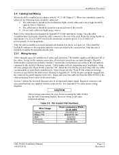
...cables and connectors. Pin Contact Part Numbers Wire Gauge Garmin P/N Military P/N AMP Positronic ITT Cannon 78 pin connectors (P691) 22-28 AWG 336-00021-00 M39029/58-360 204370-2 MC8522D 030-2042-000 GDL 69/69A Installation Manual 190-00355-02 Page 2-5 Revision E Construct the ...wiring harness according to the other units away from the GDL 69/69A to the information contained in this and the following issues should be addressed...
...cables and connectors. Pin Contact Part Numbers Wire Gauge Garmin P/N Military P/N AMP Positronic ITT Cannon 78 pin connectors (P691) 22-28 AWG 336-00021-00 M39029/58-360 204370-2 MC8522D 030-2042-000 GDL 69/69A Installation Manual 190-00355-02 Page 2-5 Revision E Construct the ...wiring harness according to the other units away from the GDL 69/69A to the information contained in this and the following issues should be addressed...
Installation Manual
Page 22
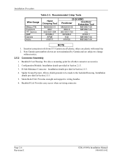
... all plastic; Spider Ground System: Allows shield grounds to be made to change without notice. 2.5.2 Connector Assembly 1. Page 2-6 Revision E GDL 69/69A Installation Manual 190-00355-02 Non-Garmin part numbers shown are not maintained by Garmin and are subject to the backshell housing. Recommended Crimp Tools Wire Gauge Military P/N Positronic ITT Cannon AMP Daniels Astro...
... all plastic; Spider Ground System: Allows shield grounds to be made to change without notice. 2.5.2 Connector Assembly 1. Page 2-6 Revision E GDL 69/69A Installation Manual 190-00355-02 Non-Garmin part numbers shown are not maintained by Garmin and are subject to the backshell housing. Recommended Crimp Tools Wire Gauge Military P/N Positronic ITT Cannon AMP Daniels Astro...

Installation Manual
Page 23
Garmin Connector Assembly GDL 69/69A Installation Manual 190-00355-02 Page 2-7 Revision E Garmin Connector Assembly Item Number (Reference Figure 2-5) Description 1 Backshell, with Config 50/78 Pin 2 PCB Assembly, Configuration Module 3 Connector, High Density, ...Screw, 4-40 x .187 FLHP100, Stainless Steel 8 Screw, 4-40 x .375, Phillips, Stainless Steel 9 Screw, 4-40 x .250, FLHP, Stainless Steel 7 6 Installation Procedure Qty Garmin Part Number 1 125-00085-00 1 012-00605-00 1 330-00185-78 1 320-00212-00 1 115-00499-03 1 115-00500-04 2 211-63234-06 3 211-60234...
Garmin Connector Assembly GDL 69/69A Installation Manual 190-00355-02 Page 2-7 Revision E Garmin Connector Assembly Item Number (Reference Figure 2-5) Description 1 Backshell, with Config 50/78 Pin 2 PCB Assembly, Configuration Module 3 Connector, High Density, ...Screw, 4-40 x .187 FLHP100, Stainless Steel 8 Screw, 4-40 x .375, Phillips, Stainless Steel 9 Screw, 4-40 x .250, FLHP, Stainless Steel 7 6 Installation Procedure Qty Garmin Part Number 1 125-00085-00 1 012-00605-00 1 330-00185-78 1 320-00212-00 1 115-00499-03 1 115-00500-04 2 211-63234-06 3 211-60234...


