Installation Instructions
Page 1
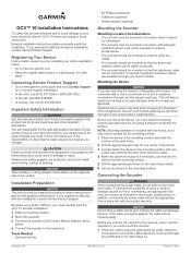
... Support. Because every boat is properly aligned, the cable should be mounted so that the transducer cable can damage the pins. GCV™ 10 Installation Instructions To obtain the best performance and to avoid damage to your boat, install the Garmin® GCV 10 device according to these instructions could result in Taiwan If you must be connected...
... Support. Because every boat is properly aligned, the cable should be mounted so that the transducer cable can damage the pins. GCV™ 10 Installation Instructions To obtain the best performance and to avoid damage to your boat, install the Garmin® GCV 10 device according to these instructions could result in Taiwan If you must be connected...
Installation Instructions
Page 2
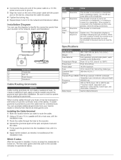
...installation hole. 3 Route the cable through your Garmin dealer or directly from 5° to 158°F) Power Input From 10 to 35 Vdc Power usage 10. 5 W maximum Fuse 4. 0 A, mini 42 Vdc, fast-acting, blade-type Compass Safe Distance 260 mm (10. 2 in. ) Transmit Power (RMS)* 500 W per element (1,500 W combined) *dependent upon transducer... use this code persists, check the wiring connections. Item À Á Â Ã Description Chartplotter GCV 10 Power Source Transducer Cable Routing Grommets NOTICE Cable routing grommets do not create a waterproof seal.
...installation hole. 3 Route the cable through your Garmin dealer or directly from 5° to 158°F) Power Input From 10 to 35 Vdc Power usage 10. 5 W maximum Fuse 4. 0 A, mini 42 Vdc, fast-acting, blade-type Compass Safe Distance 260 mm (10. 2 in. ) Transmit Power (RMS)* 500 W per element (1,500 W combined) *dependent upon transducer... use this code persists, check the wiring connections. Item À Á Â Ã Description Chartplotter GCV 10 Power Source Transducer Cable Routing Grommets NOTICE Cable routing grommets do not create a waterproof seal.


