Installation Manual
Page 11
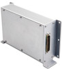
GENERAL DESCRIPTION 1.1 Introduction The GAD 43 Adapter is installed. Figure 1-1. GAD 43 Unit View GAD 43 Installation Manual 190-00899-00 Page 1-1 Rev. For attitude-based autopilots, the GAD 43 allows the existing ADI or attitude gyro to be removed when the G500/G600 system is an optional adapter for the G500/G600 Integrated Flight Decks that provides analog attitude information for use with third-party autopilot systems. It interfaces with the GDU 620 Display for configuration and alerting, and with the GRS 77 for attitude, heading, and yaw input information. B 1.
GENERAL DESCRIPTION 1.1 Introduction The GAD 43 Adapter is installed. Figure 1-1. GAD 43 Unit View GAD 43 Installation Manual 190-00899-00 Page 1-1 Rev. For attitude-based autopilots, the GAD 43 allows the existing ADI or attitude gyro to be removed when the G500/G600 system is an optional adapter for the G500/G600 Integrated Flight Decks that provides analog attitude information for use with third-party autopilot systems. It interfaces with the GDU 620 Display for configuration and alerting, and with the GRS 77 for attitude, heading, and yaw input information. B 1.
Installation Manual
Page 23
...separately. [7] Solder sleeve with pre-installed lead may be used instead of GAD 43 Connector Kit P/N 011-01990-00. [6] Not supplied - GAD 43 Installation Manual 190-00899-00 Page 3-3 Rev. Table 3-3 lists Garmin part numbers for the GAD 43 D-sub connector and the backshell assembly. Backshell Assembly Figure 3-1 thru Figure ...backshell housing using the shield block ground kit. B 3.6 Backshell Assemblies 3.6.1 Backshell Assembly and D-Subminiature Connectors The GAD 43 connector kit (P/N 011-01990-00) includes one Garmin backshell assembly and one Garmin ground adapter assembly.
...separately. [7] Solder sleeve with pre-installed lead may be used instead of GAD 43 Connector Kit P/N 011-01990-00. [6] Not supplied - GAD 43 Installation Manual 190-00899-00 Page 3-3 Rev. Table 3-3 lists Garmin part numbers for the GAD 43 D-sub connector and the backshell assembly. Backshell Assembly Figure 3-1 thru Figure ...backshell housing using the shield block ground kit. B 3.6 Backshell Assemblies 3.6.1 Backshell Assembly and D-Subminiature Connectors The GAD 43 connector kit (P/N 011-01990-00) includes one Garmin backshell assembly and one Garmin ground adapter assembly.
Installation Manual
Page 24
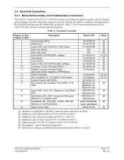
3.6.1.1 Shield Block Assembly Procedure The parts for the connector and backshell assembly for the GAD 43 installations are listed in Table 3-3. Backshell connectors give the installer the ability to terminate shield grounds at the backshell housing using the Shield Block ground kit. 9 2x 8 4 5 7 1 5x 6 2 3 4x Figure 3-1. Connector and Backshell Assembly Page 3-4 Rev. B Figure 3-2. Shielded Cable Preparation GAD 43 Installation Manual 190-00899-00 The GAD 43 connector kit (P/N 011-01990-00) includes one Garmin backshell assembly and one Garmin ground adapter assembly.
3.6.1.1 Shield Block Assembly Procedure The parts for the connector and backshell assembly for the GAD 43 installations are listed in Table 3-3. Backshell connectors give the installer the ability to terminate shield grounds at the backshell housing using the Shield Block ground kit. 9 2x 8 4 5 7 1 5x 6 2 3 4x Figure 3-1. Connector and Backshell Assembly Page 3-4 Rev. B Figure 3-2. Shielded Cable Preparation GAD 43 Installation Manual 190-00899-00 The GAD 43 connector kit (P/N 011-01990-00) includes one Garmin backshell assembly and one Garmin ground adapter assembly.

Installation Manual
Page 55
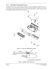
CIRCUIT BREAKER SHOULD BE LABELED AS SHOWN. 6. B THE GAD 43 SHOULD BE ON THE SAME POWER BUS AS THE AUTOPILOT. GAD 43 Power Interconnect GAD 43 Installation Manual 190-00899-00 Page C-3 Rev. GROUND DESIGNATIONS: s SHIELD BLOCK GROUND AIRFRAME GROUND 3. 'AIRCRAFT POWER 1' IS INTERNALLY DIODE ISOLATED ...FROM 'AIRCRAFT POWER 2'. 4. Figure C-1. ALL WIRES 24 AWG OR LARGER UNLESS OTHERWISE SPECIFIED. 2. CONNECTING A SECOND POWER INPUT IS OPTIONAL. 5. GAD 43 ADAPTER P431 3 AIRCRAFT POWER 1 49 AIRCRAFT GND 47 3 AIRCRAFT POWER 2 50 AIRCRAFT GND 48 22 AWG 22 AWG 4 22 AWG 22 AWG...
CIRCUIT BREAKER SHOULD BE LABELED AS SHOWN. 6. B THE GAD 43 SHOULD BE ON THE SAME POWER BUS AS THE AUTOPILOT. GAD 43 Power Interconnect GAD 43 Installation Manual 190-00899-00 Page C-3 Rev. GROUND DESIGNATIONS: s SHIELD BLOCK GROUND AIRFRAME GROUND 3. 'AIRCRAFT POWER 1' IS INTERNALLY DIODE ISOLATED ...FROM 'AIRCRAFT POWER 2'. 4. Figure C-1. ALL WIRES 24 AWG OR LARGER UNLESS OTHERWISE SPECIFIED. 2. CONNECTING A SECOND POWER INPUT IS OPTIONAL. 5. GAD 43 ADAPTER P431 3 AIRCRAFT POWER 1 49 AIRCRAFT GND 47 3 AIRCRAFT POWER 2 50 AIRCRAFT GND 48 22 AWG 22 AWG 4 22 AWG 22 AWG...