Installation Manual
Page 3
... copy of this manual or revision must contain the complete text of this copyright notice and provided further that any unauthorized commercial distribution of this guide, please e-mail: Techpubs.Salem@garmin.com. or its subsidiaries All Rights Reserved Except as expressly provided herein, no part of this manual may be viewed and to a table (5-1). GAD 43 Installation Manual 190-00899...
... copy of this manual or revision must contain the complete text of this copyright notice and provided further that any unauthorized commercial distribution of this guide, please e-mail: Techpubs.Salem@garmin.com. or its subsidiaries All Rights Reserved Except as expressly provided herein, no part of this manual may be viewed and to a table (5-1). GAD 43 Installation Manual 190-00899...
Installation Manual
Page 5
... the State of software version 2.00. GAD 43 Installation Manual 190-00899-00 Page i Rev. The preceding statement is required to be observed when comparing the information in part of Commerce (15 CFR, Chapter VII Subchapter C) and which may be included on any questions or would like additional information, please refer to our web site at www.garmin.com/prop65...
... the State of software version 2.00. GAD 43 Installation Manual 190-00899-00 Page i Rev. The preceding statement is required to be observed when comparing the information in part of Commerce (15 CFR, Chapter VII Subchapter C) and which may be included on any questions or would like additional information, please refer to our web site at www.garmin.com/prop65...
Installation Manual
Page 7
... Descriptions ...4-3 4.2.1 Power...4-3 4.2.2 Power Supply Outputs...4-3 4.2.3 Serial Data...4-3 4.2.4 Gyro Emulation Interfaces 4-4 4.2.5 Baro Correction Outputs ...4-6 4.2.6 Discretes...4-6 GAD 43 Installation Manual 190-00899-00 Page iii Rev. INSTALLATION OVERVIEW ...2-1 2.1 Introduction...2-1 2.2 Installation Materials ...2-1 2.2.1 Configurations Available ...2-1 2.2.2 Materials Required But Not Supplied 2-1 2.3 Optional Reference Material...2-1 2.4 Installation Considerations...2-1 2.4.1 Cabling and Wiring ...2-2 2.4.2 Cooling Requirements...2-2 2.4.3 Mounting Requirements...
... Descriptions ...4-3 4.2.1 Power...4-3 4.2.2 Power Supply Outputs...4-3 4.2.3 Serial Data...4-3 4.2.4 Gyro Emulation Interfaces 4-4 4.2.5 Baro Correction Outputs ...4-6 4.2.6 Discretes...4-6 GAD 43 Installation Manual 190-00899-00 Page iii Rev. INSTALLATION OVERVIEW ...2-1 2.1 Introduction...2-1 2.2 Installation Materials ...2-1 2.2.1 Configurations Available ...2-1 2.2.2 Materials Required But Not Supplied 2-1 2.3 Optional Reference Material...2-1 2.4 Installation Considerations...2-1 2.4.1 Cabling and Wiring ...2-2 2.4.2 Cooling Requirements...2-2 2.4.3 Mounting Requirements...
Installation Manual
Page 8
... 7.1 Operation ...7-1 7.2 Installation ...7-1 7.2.1 Equipment Interfaced to the GAD 43 7-1 8. Recommended Crimp Tools...3-2 Table 3-3. SYSTEM CONFIGURATION AND CHECKOUT 5-1 5.1 Post Installation Power Check ...5-1 5.2 GAD 43 Software Loading ...5-1 5.3 Initial Configuration of GAD 43 2-2 Figure 3-1. GAD 43 Unit and Connector B-3 Figure B-2. GAD 43 WXR Stabilization Interconnect C-8 LIST OF TABLES Table 2-1. Catalog Part Numbers...2-1 Table 2-2. Backshell Assembly ...3-3 Table 4-1. Gyro Emulation Types...5-3 Page iv Rev. GAD 43 Remote Mount Gyro Replacement...
... 7.1 Operation ...7-1 7.2 Installation ...7-1 7.2.1 Equipment Interfaced to the GAD 43 7-1 8. Recommended Crimp Tools...3-2 Table 3-3. SYSTEM CONFIGURATION AND CHECKOUT 5-1 5.1 Post Installation Power Check ...5-1 5.2 GAD 43 Software Loading ...5-1 5.3 Initial Configuration of GAD 43 2-2 Figure 3-1. GAD 43 Unit and Connector B-3 Figure B-2. GAD 43 WXR Stabilization Interconnect C-8 LIST OF TABLES Table 2-1. Catalog Part Numbers...2-1 Table 2-2. Backshell Assembly ...3-3 Table 4-1. Gyro Emulation Types...5-3 Page iv Rev. GAD 43 Remote Mount Gyro Replacement...
Installation Manual
Page 9
...) and is current at www.garmin.com using their Garmin-provided user name and password. The table is subject to -date bulletin and advisory information on the Garmin Dealer Resource web site at the time of publication of the modification. MOD LEVEL SERVICE BULLETIN NUMBER SERVICE BULLETIN DATE PURPOSE OF MODIFICATION GAD 43 Installation Manual 190-00899-00 Page v Rev. GAD 43 HARDWARE MOD LEVEL HISTORY The following...
...) and is current at www.garmin.com using their Garmin-provided user name and password. The table is subject to -date bulletin and advisory information on the Garmin Dealer Resource web site at the time of publication of the modification. MOD LEVEL SERVICE BULLETIN NUMBER SERVICE BULLETIN DATE PURPOSE OF MODIFICATION GAD 43 Installation Manual 190-00899-00 Page v Rev. GAD 43 HARDWARE MOD LEVEL HISTORY The following...
Installation Manual
Page 11
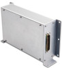
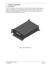
1. GAD 43 Unit View GAD 43 Installation Manual 190-00899-00 Page 1-1 Rev. GENERAL DESCRIPTION 1.1 Introduction The GAD 43 Adapter is installed. B Figure 1-1. For attitude-based autopilots, the GAD 43 allows the existing ADI or attitude gyro to be removed when the G500/G600 system is an optional adapter for the G500/G600 Integrated Flight Decks that provides analog attitude information for use with third-party autopilot systems. It interfaces with the GDU 620 Display for configuration and alerting, and with the GRS 77 for attitude, heading, and yaw input information.
1. GAD 43 Unit View GAD 43 Installation Manual 190-00899-00 Page 1-1 Rev. GENERAL DESCRIPTION 1.1 Introduction The GAD 43 Adapter is installed. B Figure 1-1. For attitude-based autopilots, the GAD 43 allows the existing ADI or attitude gyro to be removed when the G500/G600 system is an optional adapter for the G500/G600 Integrated Flight Decks that provides analog attitude information for use with third-party autopilot systems. It interfaces with the GDU 620 Display for configuration and alerting, and with the GRS 77 for attitude, heading, and yaw input information.
Installation Manual
Page 12
... information. Page 1-2 Rev. one set of pitch and roll analog outputs. An input for AC reference voltage is also provided and is used for signal polarity. 1.3.3.3 Analog Pitch / Roll The GAD 43 has one each for pitch, roll, and heading. B GAD 43 Installation Manual 190-00899-00 Various analog interfaces (including ARINC 407) are provided for the emulation of panel mount gyros. These outputs are also supported. Power supply outputs...
... information. Page 1-2 Rev. one set of pitch and roll analog outputs. An input for AC reference voltage is also provided and is used for signal polarity. 1.3.3.3 Analog Pitch / Roll The GAD 43 has one each for pitch, roll, and heading. B GAD 43 Installation Manual 190-00899-00 Various analog interfaces (including ARINC 407) are provided for the emulation of panel mount gyros. These outputs are also supported. Power supply outputs...
Installation Manual
Page 13
... be used for radar stabilization. 1.3.4 Discrete Inputs and Outputs The GAD 43 has one active-low discrete input and two active-low discrete outputs. B 1.3.3.5 Radar Stabilization The GAD 43 provides two 2-wire (one for pitch and one of the discrete outputs are available to support a wide-variety of configurations. 1.4 Technical Specifications 1.4.1 Environmental Qualification Form It is available directly from Garmin under the following part number: GAD 43 Environmental Qualification Form, EQF, Garmin part number 005...
... be used for radar stabilization. 1.3.4 Discrete Inputs and Outputs The GAD 43 has one active-low discrete input and two active-low discrete outputs. B 1.3.3.5 Radar Stabilization The GAD 43 provides two 2-wire (one for pitch and one of the discrete outputs are available to support a wide-variety of configurations. 1.4 Technical Specifications 1.4.1 Environmental Qualification Form It is available directly from Garmin under the following part number: GAD 43 Environmental Qualification Form, EQF, Garmin part number 005...
Installation Manual
Page 16
... a deviation from SAE Aerospace Standard AS 8001 to use RTCA DO-160E instead of SAE AS 396B for Airborne Equipment. 2. B GAD 43 Installation Manual 190-00899-00 Garmin was granted a deviation from SAE Aerospace Standard SAE 402A to use environmental test conditions and procedures from TSO-C4c to use SAE AS 8001 instead of RTCA DO-138 as the...
... a deviation from SAE Aerospace Standard AS 8001 to use RTCA DO-160E instead of SAE AS 396B for Airborne Equipment. 2. B GAD 43 Installation Manual 190-00899-00 Garmin was granted a deviation from SAE Aerospace Standard SAE 402A to use environmental test conditions and procedures from TSO-C4c to use SAE AS 8001 instead of RTCA DO-138 as the...
Installation Manual
Page 17
....8101 GAD 43 Installation Manual 190-00899-00 Page 1-7 Rev. For assistance in materials or workmanship for any package purchased through online auctions are not accepted for parts or labor, provided that fail in normal use. To obtain warranty service, an original or copy of the sales receipt from Garmin. Garmin will be made at its sole option, repair or replace any...
....8101 GAD 43 Installation Manual 190-00899-00 Page 1-7 Rev. For assistance in materials or workmanship for any package purchased through online auctions are not accepted for parts or labor, provided that fail in normal use. To obtain warranty service, an original or copy of the sales receipt from Garmin. Garmin will be made at its sole option, repair or replace any...
Installation Manual
Page 19
... existing remote-mounted or panel-mounted gyro can be removed, and the GAD 43 will be considered for making retro-fit installations that must be installed to fit each installation. The following part numbers. Catalog Part Numbers Model GAD 43 Unit P/N 011-01970-00 Catalog P/N Without Installation Kit 010-00724-00 Catalog P/N With Installation Kit (G600) 010-00724-01 Catalog P/N With Installation Kit (G500) 010-00724-02 Table 2-2. Installation Accessories Item GAD 43 Connector Kit Garmin...
... existing remote-mounted or panel-mounted gyro can be removed, and the GAD 43 will be considered for making retro-fit installations that must be installed to fit each installation. The following part numbers. Catalog Part Numbers Model GAD 43 Unit P/N 011-01970-00 Catalog P/N Without Installation Kit 010-00724-00 Catalog P/N With Installation Kit (G600) 010-00724-01 Catalog P/N With Installation Kit (G500) 010-00724-02 Table 2-2. Installation Accessories Item GAD 43 Connector Kit Garmin...

Installation Manual
Page 20
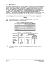
... connections unless otherwise specified by the aircraft manufacturer or Garmin. In cases where some installations have more than one unit on aircraft circuit breaker layout, length of wiring, current draw of the GAD 43 is restricted to locations in the GAD 43 Environmental Qualification Form (EQF), P/N 005-00496-07. Avoid sharp bends in cabling and routing near aircraft control cables. 2.4.2 Cooling Requirements The GAD 43 has no cooling requirements. 2.4.3 Mounting...
... connections unless otherwise specified by the aircraft manufacturer or Garmin. In cases where some installations have more than one unit on aircraft circuit breaker layout, length of wiring, current draw of the GAD 43 is restricted to locations in the GAD 43 Environmental Qualification Form (EQF), P/N 005-00496-07. Avoid sharp bends in cabling and routing near aircraft control cables. 2.4.2 Cooling Requirements The GAD 43 has no cooling requirements. 2.4.3 Mounting...

Installation Manual
Page 21
... enter configuration mode on the GAD 43 unit. Refer to locations in the aircraft that the slide-lock is restricted to Table 3-2 for power. Cabling must also be fabricated to fit each particular aircraft. 3.4 Unit Replacement Whenever the GAD 43 is removed and reinstalled, verify that are consistent with the DO-160E categories defined in the GAD 43 Environmental Qualification Form (EQF), P/N 005-00496-07. Use 22 or 24 AWG wire...
... enter configuration mode on the GAD 43 unit. Refer to locations in the aircraft that the slide-lock is restricted to Table 3-2 for power. Cabling must also be fabricated to fit each particular aircraft. 3.4 Unit Replacement Whenever the GAD 43 is removed and reinstalled, verify that are consistent with the DO-160E categories defined in the GAD 43 Environmental Qualification Form (EQF), P/N 005-00496-07. Use 22 or 24 AWG wire...
Installation Manual
Page 22
... of all input and output signals. Strip all of the cables. Route and secure the cable run from the GAD 43 to the other units away from sources of cables and connectors. Socket Contact Part Numbers Wire Gauge Garmin P/N Military P/N AMP Positronic ITT Cannon 50-pin connector (P431) 20-24 AWG 336-00022-00 M39029/63-368 N/A N/A N/A Table 3-2. See APPENDIX C for interconnect wiring diagrams. CAUTION Check wiring connections for installation of electrical...
... of all input and output signals. Strip all of the cables. Route and secure the cable run from the GAD 43 to the other units away from sources of cables and connectors. Socket Contact Part Numbers Wire Gauge Garmin P/N Military P/N AMP Positronic ITT Cannon 50-pin connector (P431) 20-24 AWG 336-00022-00 M39029/63-368 N/A N/A N/A Table 3-2. See APPENDIX C for interconnect wiring diagrams. CAUTION Check wiring connections for installation of electrical...
Installation Manual
Page 23
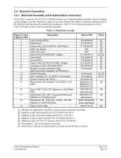
...SS/P, w/Nylon 10 Connector, D-Sub, 50 Socket (P431) 11 Multiple Conductor Shielded Cable (See Interconnect Diagrams, APPENDIX C) 12 Shield Terminator 13 Wire, Insulated, 20 - 22 AWG (3" max length) 14 Socket ...installed lead may be used instead of GAD 43 Connector Kit P/N 011-01990-00. [6] Not supplied - Table 3-3 lists Garmin part numbers for the GAD 43 D-sub connector and the backshell assembly. 3.6 Backshell Assemblies 3.6.1 Backshell Assembly and D-Subminiature Connectors The GAD 43 connector kit (P/N 011-01990-00) includes one Garmin backshell assembly and one Garmin...
...SS/P, w/Nylon 10 Connector, D-Sub, 50 Socket (P431) 11 Multiple Conductor Shielded Cable (See Interconnect Diagrams, APPENDIX C) 12 Shield Terminator 13 Wire, Insulated, 20 - 22 AWG (3" max length) 14 Socket ...installed lead may be used instead of GAD 43 Connector Kit P/N 011-01990-00. [6] Not supplied - Table 3-3 lists Garmin part numbers for the GAD 43 D-sub connector and the backshell assembly. 3.6 Backshell Assemblies 3.6.1 Backshell Assembly and D-Subminiature Connectors The GAD 43 connector kit (P/N 011-01990-00) includes one Garmin backshell assembly and one Garmin...
Installation Manual
Page 26
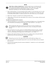
...). While holding the slide lock in place, attach the connector / slide lock to use , refer to Raychem installation procedure. 3. Place the smooth side of items 12 and 13. B GAD 43 Installation Manual 190-00899-00 Assemble the backshell onto the connector: 1. CAUTION When mounting the slide lock, use with solder sleeves. Slide a shield terminator (12) onto the prepared cable assembly (11) and connect the wire...
...). While holding the slide lock in place, attach the connector / slide lock to use , refer to Raychem installation procedure. 3. Place the smooth side of items 12 and 13. B GAD 43 Installation Manual 190-00899-00 Assemble the backshell onto the connector: 1. CAUTION When mounting the slide lock, use with solder sleeves. Slide a shield terminator (12) onto the prepared cable assembly (11) and connect the wire...

Installation Manual
Page 27
... ring terminal, second ring terminal if needed, before finally inserting the screw into the tapped holes on the shield block. 3.7 Unit Installation The GAD 43 is preferred that only three wires are terminated in each ring terminal to ensure a good electrical connection. 6. Terminate the ring terminals to approved aircraft maintenance manuals or manual supplements for actual aircraft maintenance requirements. NOTE Each tapped hole...
... ring terminal, second ring terminal if needed, before finally inserting the screw into the tapped holes on the shield block. 3.7 Unit Installation The GAD 43 is preferred that only three wires are terminated in each ring terminal to ensure a good electrical connection. 6. Terminate the ring terminals to approved aircraft maintenance manuals or manual supplements for actual aircraft maintenance requirements. NOTE Each tapped hole...
Installation Manual
Page 32
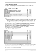
... of emulating numerous standard attitude gyro interfaces described below. The GAD 43 provides AC pitch and roll outputs intended for wiring interconnect information to Section 5.3.1.1 for 10 VAC reference voltage is also provided. The GAD 43 provides synchro pitch, roll and heading outputs. Refer to support this conversion. B GAD 43 Installation Manual 190-00899-00 An input for configuration information. 4.2.4.2 Synchro (ARINC 407) Outputs Pin Name HDG SYNCHRO OUT X HDG SYNCHRO...
... of emulating numerous standard attitude gyro interfaces described below. The GAD 43 provides AC pitch and roll outputs intended for wiring interconnect information to Section 5.3.1.1 for 10 VAC reference voltage is also provided. The GAD 43 provides synchro pitch, roll and heading outputs. Refer to support this conversion. B GAD 43 Installation Manual 190-00899-00 An input for configuration information. 4.2.4.2 Synchro (ARINC 407) Outputs Pin Name HDG SYNCHRO OUT X HDG SYNCHRO...
Installation Manual
Page 34
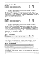
... these output pins will be used for yaw rate output and baro correction output. A configuration of 100, 200, 333, and 666 mVDC/deg/sec. Notes: [1] Multi-function pins used for barometric correction as viewed from 0 to 5 VDC based on the barometric setting displayed on the output when active. This interface is Active-Low, producing a low (ground) on the GDU 620. Refer to be used in installations with configurable values...
... these output pins will be used for yaw rate output and baro correction output. A configuration of 100, 200, 333, and 666 mVDC/deg/sec. Notes: [1] Multi-function pins used for barometric correction as viewed from 0 to 5 VDC based on the barometric setting displayed on the output when active. This interface is Active-Low, producing a low (ground) on the GDU 620. Refer to be used in installations with configurable values...

Installation Manual
Page 37
... inserted in configuration mode, the left display has only one page that there is installed in configuration mode by pressing and holding the ENT button while applying power. Ensure wiring is no interference. Verify that are correct. 5.2 GAD 43 Software Loading Prior to using the GAD 43, the required GAD 43 software should be loaded as desired, external data sources must be configured, and miscellaneous options must be set up. To do this an Installer Unlock Card (P/N 010...
... inserted in configuration mode, the left display has only one page that there is installed in configuration mode by pressing and holding the ENT button while applying power. Ensure wiring is no interference. Verify that are correct. 5.2 GAD 43 Software Loading Prior to using the GAD 43, the required GAD 43 software should be loaded as desired, external data sources must be configured, and miscellaneous options must be set up. To do this an Installer Unlock Card (P/N 010...

