

Maintenance Manual
Page 1
GAD 42 MAINTENANCE MANUAL GARMIN International, Inc. 1200 E. 151st Street Olathe, KS 66062 USA 190-00159-01, Revision A July 2001
GAD 42 MAINTENANCE MANUAL GARMIN International, Inc. 1200 E. 151st Street Olathe, KS 66062 USA 190-00159-01, Revision A July 2001
Maintenance Manual
Page 2
... Telephone: 913-397-8200 Dealer Line: 1-800-800-1420 Web Site Address: www.garmin.com RECORD OF REVISIONS REVISION A REVISION DATE 07/03/01 Description Initial Release ECO # ----- A Insertion Date By GAD 42 MAINTENANCE MANUAL P/N 190-00159-01 Page 1 Rev. © Copyright 2001 GARMIN Corporation All Rights Reserved Except as expressly provided below, no part of...
... Telephone: 913-397-8200 Dealer Line: 1-800-800-1420 Web Site Address: www.garmin.com RECORD OF REVISIONS REVISION A REVISION DATE 07/03/01 Description Initial Release ECO # ----- A Insertion Date By GAD 42 MAINTENANCE MANUAL P/N 190-00159-01 Page 1 Rev. © Copyright 2001 GARMIN Corporation All Rights Reserved Except as expressly provided below, no part of...
Maintenance Manual
Page 3
... CFR, Chapter VII, Subchapter C) and which may be exported, released, or disclosed to $1,000,000 under Section 2410 of the Export Administration Act of 1979. GAD 42 MAINTENANCE MANUAL P/N 190-00159-01 Page 2 Rev. A violation of the EAR may not be subject to a penalty of up to 10 years imprisonment and a fine of up...
... CFR, Chapter VII, Subchapter C) and which may be exported, released, or disclosed to $1,000,000 under Section 2410 of the Export Administration Act of 1979. GAD 42 MAINTENANCE MANUAL P/N 190-00159-01 Page 2 Rev. A violation of the EAR may not be subject to a penalty of up to 10 years imprisonment and a fine of up...
Maintenance Manual
Page 4
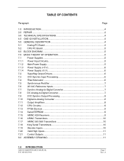
A TABLE OF CONTENTS Paragraph Page 1.0 INTRODUCTION ...4 2.0 REPAIR ...4 3.0 TECHNICAL SPECIFICATIONS 4 4.0 GAD 42 INSTALLATION 4 5.0 GENERAL DESCRIPTION 4 5.1 Analog PC Board 4 5.2 CPU PC Board 5 6.0 BLOCK DIAGRAM 5 7.0 BASIC THEORY OF OPERATION 5 7.1 Power Supplies 5 7.1.1 Power Input Circuitry 5 7.1.2 Main Power Supply 5 7.1.3 Power Supply (+5 V... 10 7.18 King Serial Transmitters 10 7.19 Discrete Inputs 10 7.20 Valid High Inputs 11 7.21 Control Outputs 11 8.0 ASSEMBLY DRAWING 11 1.0 INTRODUCTION GAD 42 MAINTENANCE MANUAL P/N 190-00159-01 Page 3 Rev.
A TABLE OF CONTENTS Paragraph Page 1.0 INTRODUCTION ...4 2.0 REPAIR ...4 3.0 TECHNICAL SPECIFICATIONS 4 4.0 GAD 42 INSTALLATION 4 5.0 GENERAL DESCRIPTION 4 5.1 Analog PC Board 4 5.2 CPU PC Board 5 6.0 BLOCK DIAGRAM 5 7.0 BASIC THEORY OF OPERATION 5 7.1 Power Supplies 5 7.1.1 Power Input Circuitry 5 7.1.2 Main Power Supply 5 7.1.3 Power Supply (+5 V... 10 7.18 King Serial Transmitters 10 7.19 Discrete Inputs 10 7.20 Valid High Inputs 11 7.21 Control Outputs 11 8.0 ASSEMBLY DRAWING 11 1.0 INTRODUCTION GAD 42 MAINTENANCE MANUAL P/N 190-00159-01 Page 3 Rev.

Maintenance Manual
Page 5
... header board interface connectors provide interconnect to GARMIN for service. 3.0 TECHNICAL SPECIFICATIONS Technical specifications for the GAD 42 are listed in the GAD 42 Installation Manual, P/N 190-00159-00. 4.0 GAD 42 INSTALLATION Installation information for the unit is a microprocessor based input/output (I /O circuitry. A Return faulty units to the CPU PC board. GAD 42 MAINTENANCE MANUAL P/N 190-00159-01 Page 4 Rev. Functions provided...
... header board interface connectors provide interconnect to GARMIN for service. 3.0 TECHNICAL SPECIFICATIONS Technical specifications for the GAD 42 are listed in the GAD 42 Installation Manual, P/N 190-00159-00. 4.0 GAD 42 INSTALLATION Installation information for the unit is a microprocessor based input/output (I /O circuitry. A Return faulty units to the CPU PC board. GAD 42 MAINTENANCE MANUAL P/N 190-00159-01 Page 4 Rev. Functions provided...
Maintenance Manual
Page 6
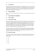
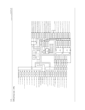
... kHz and producing the following output voltages: • +20 V • +12 V • -12 V • -20 V • +34 V GAD 42 MAINTENANCE MANUAL P/N 190-00159-01 Page 5 Rev. The power-input filter is a transient suppression zener. Power input is also routed through a three-amp superflag input fuse. A... connectors provide interconnect to the Analog PC board assembly. 6.0 BLOCK DIAGRAM Figure 1, page 12, shows a block diagram of the GAD 42 to the unit power supplies. Digital and discrete I/O circuitry is a transient suppression zener. This same inductor forms an output low pass...
... kHz and producing the following output voltages: • +20 V • +12 V • -12 V • -20 V • +34 V GAD 42 MAINTENANCE MANUAL P/N 190-00159-01 Page 5 Rev. The power-input filter is a transient suppression zener. Power input is also routed through a three-amp superflag input fuse. A... connectors provide interconnect to the Analog PC board assembly. 6.0 BLOCK DIAGRAM Figure 1, page 12, shows a block diagram of the GAD 42 to the unit power supplies. Digital and discrete I/O circuitry is a transient suppression zener. This same inductor forms an output low pass...
Maintenance Manual
Page 7
... controlled by identical circuitry, only the 11.8 Vac heading inputs, HEADING X and HEADING Y are grounded in the GAD 42. The FET switches are turned on, causing a bias voltage to be developed across the gate-source junction of each.... 7.1.4 Power Supply (-5 V) The -5 V power supply provides bias voltage for the CMOS analog switches in the GAD 42. The switcher along with filter circuitry produces a smoothed and filtered +5 V. Frequency compensation for the +5 V Power ... ripple voltage. All Z synchro inputs are discussed here. GAD 42 MAINTENANCE MANUAL P/N 190-00159-01 Page 6 Rev.
... controlled by identical circuitry, only the 11.8 Vac heading inputs, HEADING X and HEADING Y are grounded in the GAD 42. The FET switches are turned on, causing a bias voltage to be developed across the gate-source junction of each.... 7.1.4 Power Supply (-5 V) The -5 V power supply provides bias voltage for the CMOS analog switches in the GAD 42. The switcher along with filter circuitry produces a smoothed and filtered +5 V. Frequency compensation for the +5 V Power ... ripple voltage. All Z synchro inputs are discussed here. GAD 42 MAINTENANCE MANUAL P/N 190-00159-01 Page 6 Rev.
Maintenance Manual
Page 8
... to two circuits. First is a buffer amplifier: its output is used to monitor the AC reference input amplitude, and also is a -90 Degree Phase Shift. GAD 42 MAINTENANCE MANUAL P/N 190-00159-01 Page 7 Rev.
... to two circuits. First is a buffer amplifier: its output is used to monitor the AC reference input amplitude, and also is a -90 Degree Phase Shift. GAD 42 MAINTENANCE MANUAL P/N 190-00159-01 Page 7 Rev.
Maintenance Manual
Page 9
...a unity-gain buffer amp, a high-voltage op-amp, and inverting push-pull Darlington driver transistors all DC voltage monitoring in the GAD 42. The SELECTED CRS DRIVE X/COS and SELECTED CRS DRIVE Y/SIN outputs have an additional circuit element not present on each input. 7.9... determines the angle information to be present during certain operating conditions. This element is 4.7 Vac. It is possible due to an indicator. GAD 42 MAINTENANCE MANUAL P/N 190-00159-01 Page 8 Rev. The negative voltages are protected from negative or over -voltage transients by an output capacitor. The...
...a unity-gain buffer amp, a high-voltage op-amp, and inverting push-pull Darlington driver transistors all DC voltage monitoring in the GAD 42. The SELECTED CRS DRIVE X/COS and SELECTED CRS DRIVE Y/SIN outputs have an additional circuit element not present on each input. 7.9... determines the angle information to be present during certain operating conditions. This element is 4.7 Vac. It is possible due to an indicator. GAD 42 MAINTENANCE MANUAL P/N 190-00159-01 Page 8 Rev. The negative voltages are protected from negative or over -voltage transients by an output capacitor. The...
Maintenance Manual
Page 10
... is used to FPGA "B" input. The VPP program voltage for RS-422 format input and output, and by two D flip-flop IC's. GAD 42 MAINTENANCE MANUAL P/N 190-00159-01 Page 9 Rev. This causes Vcc to 16 MHz. The serial data bus to the EEPROM is shared with the DC A/D converter described... data when present on a different PNP output transistor. A flash memory device contains unit software code, and can then pass data. 7.12 CPU Circuitry The GAD 42 CPU board contains the CPU which is clocked at the 12 kHz output of the FPGAs (FPGA1) contains the GPS ARINC 429 and NAV ARINC...
... is used to FPGA "B" input. The VPP program voltage for RS-422 format input and output, and by two D flip-flop IC's. GAD 42 MAINTENANCE MANUAL P/N 190-00159-01 Page 9 Rev. This causes Vcc to 16 MHz. The serial data bus to the EEPROM is shared with the DC A/D converter described... data when present on a different PNP output transistor. A flash memory device contains unit software code, and can then pass data. 7.12 CPU Circuitry The GAD 42 CPU board contains the CPU which is clocked at the 12 kHz output of the FPGAs (FPGA1) contains the GPS ARINC 429 and NAV ARINC...

Maintenance Manual
Page 11
... a resistance from the FPGA is provided by a zener diode. 7.18 King Serial Transmitters The King serial data and clock transmitters are within their feedback loops. GAD 42 MAINTENANCE MANUAL P/N 190-00159-01 Page 10 Rev. During transmission of op-amps which drive push-pull transistor pairs that are located on the CPU board. King...
... a resistance from the FPGA is provided by a zener diode. 7.18 King Serial Transmitters The King serial data and clock transmitters are within their feedback loops. GAD 42 MAINTENANCE MANUAL P/N 190-00159-01 Page 10 Rev. During transmission of op-amps which drive push-pull transistor pairs that are located on the CPU board. King...
Maintenance Manual
Page 12
... base current to a transistor through a resistor to a voltage less than 10 V, no base current can flow, and the transistor is grounded through a discrete input latch. GAD 42 MAINTENANCE MANUAL P/N 190-00159-01 Page 11 Rev. If the current through a resistor is shorted to aircraft power voltage over -current protection. When the HDG_VALID_HI input pin... connected to Vcc through the resistor exceeds about 0.5 A, enough voltage is connected to ground. This turns on Q581. A diode provides transient voltage protection for the GAD 42.
... base current to a transistor through a resistor to a voltage less than 10 V, no base current can flow, and the transistor is grounded through a discrete input latch. GAD 42 MAINTENANCE MANUAL P/N 190-00159-01 Page 11 Rev. If the current through a resistor is shorted to aircraft power voltage over -current protection. When the HDG_VALID_HI input pin... connected to Vcc through the resistor exceeds about 0.5 A, enough voltage is connected to ground. This turns on Q581. A diode provides transient voltage protection for the GAD 42.
Maintenance Manual
Page 13
... ARINC 561/568 DATA ARINC 561/568 SYNC DRIVER LEVEL SHIFT ARINC 561/568 CONTINUOUS CLOCK KING SERIAL DATA KING SERIAL CLOCK KING SERIAL SYNC GAD 42 MAINTENANCE MANUAL P/N 190-00159-01 Figure 1. GAD 42 Block Diagram Page 12 Rev.
... ARINC 561/568 DATA ARINC 561/568 SYNC DRIVER LEVEL SHIFT ARINC 561/568 CONTINUOUS CLOCK KING SERIAL DATA KING SERIAL CLOCK KING SERIAL SYNC GAD 42 MAINTENANCE MANUAL P/N 190-00159-01 Figure 1. GAD 42 Block Diagram Page 12 Rev.
Maintenance Manual
Page 14
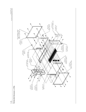
...-00 (2 PLCS) END PLATE 115-00265-00 SIDE EXTRUSION 135-00007-01 (2 PLCS) INSULATOR COVER 250-00064-00 (2 PLCS) BOARD HEADERS 334-00039-00 (3 PLCS) GAD 42 MAINTENANCE MANUAL P/N 190-00159-01 COVER 115-00266-00 INSULATOR COVER (2 PLCS) 250-00064-00 (REF) INSIDE SURFACE ONLY SCREW 211-632340-06 (4 PLCS) ANALOG BOARD 012...-00 SCREW 211-602340-08 (33 PLCS) CPU BOARD 012-00299-00 HEX STANDOFF 214-00004-00 (4 PLCS) HEX SPACER 214-00020-04 (4 PLCS) Figure 2. A GAD 42 Assembly Drawing Page 13 Rev.
...-00 (2 PLCS) END PLATE 115-00265-00 SIDE EXTRUSION 135-00007-01 (2 PLCS) INSULATOR COVER 250-00064-00 (2 PLCS) BOARD HEADERS 334-00039-00 (3 PLCS) GAD 42 MAINTENANCE MANUAL P/N 190-00159-01 COVER 115-00266-00 INSULATOR COVER (2 PLCS) 250-00064-00 (REF) INSIDE SURFACE ONLY SCREW 211-632340-06 (4 PLCS) ANALOG BOARD 012...-00 SCREW 211-602340-08 (33 PLCS) CPU BOARD 012-00299-00 HEX STANDOFF 214-00004-00 (4 PLCS) HEX SPACER 214-00020-04 (4 PLCS) Figure 2. A GAD 42 Assembly Drawing Page 13 Rev.


