
Pilots Guide
Page 9
B Garmin G600 Pilot's Guide vii Sec 6 Annun. & Alerts Sec 7 Symbols Sec 8 Glossary Appendix A Appendix B Index Contents Foreword Sec 1 System Sec 2 PFD Sec 3 MFD Sec 4 Hazard ... 1.3.1 Using the Page Menus 1-14 1.3.1.1 Navigating a Menu 1-15 1.3.2 Using the Soft Key Controls 1-15 1.3.3 System Settings 1-16 1.3.4 Display Backlighting 1-19 1.3.5 Dual GDU 620 Installations 1-19 1.3.5.1 Crossfill Information 1-19 1.3.5.2 Crossfill Selection 1-20 2 Primary Flight Display (PFD 2-1 2.1 PFD Soft Key Map 2-2 2.2 Airspeed Indicator 2-2 2.2.1 Markings 2-3 190-00601-02 Rev.
B Garmin G600 Pilot's Guide vii Sec 6 Annun. & Alerts Sec 7 Symbols Sec 8 Glossary Appendix A Appendix B Index Contents Foreword Sec 1 System Sec 2 PFD Sec 3 MFD Sec 4 Hazard ... 1.3.1 Using the Page Menus 1-14 1.3.1.1 Navigating a Menu 1-15 1.3.2 Using the Soft Key Controls 1-15 1.3.3 System Settings 1-16 1.3.4 Display Backlighting 1-19 1.3.5 Dual GDU 620 Installations 1-19 1.3.5.1 Crossfill Information 1-19 1.3.5.2 Crossfill Selection 1-20 2 Primary Flight Display (PFD 2-1 2.1 PFD Soft Key Map 2-2 2.2 Airspeed Indicator 2-2 2.2.1 Markings 2-3 190-00601-02 Rev.

Pilots Guide
Page 11
B Garmin G600 Pilot's Guide ix Foreword Sec 1 System Sec 2 PFD Sec 3 MFD Sec 4 Hazard Avoidance Features Sec 5 Additional 3.4.1 System Settings 3-46 3.4.1.1 Display Brightness 3-47 3.4.1.2 Airspeed Reference Marks 3-48 3.4.1.3 Synchronization (Dual Installations Only 3-49 3.4.1.4 Date and Time 3-50 3.4.1.5 MFD Display Units 3-52 3.4.1.6 System Display Units 3-52 3.4.2 XM Information (Optional 3-54 3.4.3 XM Entertainment Radio (Optional 3-55...
B Garmin G600 Pilot's Guide ix Foreword Sec 1 System Sec 2 PFD Sec 3 MFD Sec 4 Hazard Avoidance Features Sec 5 Additional 3.4.1 System Settings 3-46 3.4.1.1 Display Brightness 3-47 3.4.1.2 Airspeed Reference Marks 3-48 3.4.1.3 Synchronization (Dual Installations Only 3-49 3.4.1.4 Date and Time 3-50 3.4.1.5 MFD Display Units 3-52 3.4.1.6 System Display Units 3-52 3.4.2 XM Information (Optional 3-54 3.4.3 XM Entertainment Radio (Optional 3-55...

Pilots Guide
Page 16
...navigational information, and a moving map all displayed on dual 6.5" color screens. LRUs have a modular design and can be installed directly behind the instrument panel or in the G600 system. This design greatly eases troubleshooting and maintenance of sub-units or Line Replaceable Units (LRUs). Foreword System Sec 1 PFD... of the GDU 620 as integrated in a separate avionics bay if desired. Sec 6 Symbols Sec 7 Appendix A Glossary Sec 8 Index Appendix B 1-2 Garmin G600 Pilot's Guide 190-00601-02 Rev. A failure or problem can be isolated to the system's operation. The...
...navigational information, and a moving map all displayed on dual 6.5" color screens. LRUs have a modular design and can be installed directly behind the instrument panel or in the G600 system. This design greatly eases troubleshooting and maintenance of sub-units or Line Replaceable Units (LRUs). Foreword System Sec 1 PFD... of the GDU 620 as integrated in a separate avionics bay if desired. Sec 6 Symbols Sec 7 Appendix A Glossary Sec 8 Index Appendix B 1-2 Garmin G600 Pilot's Guide 190-00601-02 Rev. A failure or problem can be isolated to the system's operation. The...

Pilots Guide
Page 30
Sec 6 Symbols Sec 7 Appendix A Glossary Sec 8 Index Appendix B Figure 1-17 System Setup Page 1-16 Garmin G600 Pilot's Guide 190-00601-02 Rev. Dual installations only • Date/Time (Date, Time, Time Format, and Time Offset) • MFD Display Units (Distance/Speed and Altitude/Vertical Speed) • System Display Units... Brightness (Mode and Level) • Airspeed References (Glide, Vr, Vx, and Vy) • Dual Unit Synchronization (CDI and Baro) - B Foreword System Sec 1 1.3.3 System Settings G600 system settings are managed from the Aux Mode System Setup Page.
Sec 6 Symbols Sec 7 Appendix A Glossary Sec 8 Index Appendix B Figure 1-17 System Setup Page 1-16 Garmin G600 Pilot's Guide 190-00601-02 Rev. Dual installations only • Date/Time (Date, Time, Time Format, and Time Offset) • MFD Display Units (Distance/Speed and Altitude/Vertical Speed) • System Display Units... Brightness (Mode and Level) • Airspeed References (Glide, Vr, Vx, and Vy) • Dual Unit Synchronization (CDI and Baro) - B Foreword System Sec 1 1.3.3 System Settings G600 system settings are managed from the Aux Mode System Setup Page.

Pilots Guide
Page 33
... conditions. Manual backlighting adjustment can be set up to select "AUTO" or "MANUAL." 4) Press ENT. 1.3.5 Dual GDU 620 Installations Dual GDU 620 units when connected in the aircraft may be adjusted automatically or manually. B Garmin G600 Pilot's Guide 1-19 Appendix B Index Sec 2 PFD Sec 3 MFD Sec 4 Hazard Avoidance Features Sec 5 Additional Sec 6 Annun...
... conditions. Manual backlighting adjustment can be set up to select "AUTO" or "MANUAL." 4) Press ENT. 1.3.5 Dual GDU 620 Installations Dual GDU 620 units when connected in the aircraft may be adjusted automatically or manually. B Garmin G600 Pilot's Guide 1-19 Appendix B Index Sec 2 PFD Sec 3 MFD Sec 4 Hazard Avoidance Features Sec 5 Additional Sec 6 Annun...

Pilots Guide
Page 41
B Garmin G600 Pilot's Guide 2-5 Glide Reference Marker Vr Reference Marker Vx Reference Marker Vy Reference Marker Figure 2-8 Reference Speeds 2.3 Attitude Indicator Attitude information is repowered. The Attitude ... Sec 8 Glossary Appendix A Appendix B Index 190-00601-02 Rev. When active (on the first page of the airspeed scale. The values you set during the installation process, but can be changed and turned on/off from the System Setup page on ), the Vspeeds are retained when the unit is displayed over...
B Garmin G600 Pilot's Guide 2-5 Glide Reference Marker Vr Reference Marker Vx Reference Marker Vy Reference Marker Figure 2-8 Reference Speeds 2.3 Attitude Indicator Attitude information is repowered. The Attitude ... Sec 8 Glossary Appendix A Appendix B Index 190-00601-02 Rev. When active (on the first page of the airspeed scale. The values you set during the installation process, but can be changed and turned on/off from the System Setup page on ), the Vspeeds are retained when the unit is displayed over...

Pilots Guide
Page 42
...to indicate lateral acceleration. Sec 6 Symbols Sec 7 Appendix A Glossary Sec 8 Index Appendix B Figure 2-11 Ground Pointer Figure 2-12 Sky Pointer 2-6 Garmin G600 Pilot's Guide 190-00601-02 Rev. One bar displacement (as shown below and 45° above the horizon line, minor pitch marks occur every 2.5°... numeric labels are set by the position of the pointer on a traditional Slip/Skid Indicator. Slip/skid is indicated by the installer to the artificial horizon while the aircraft is banking. In Ground Pointer mode, the Roll Scale and Roll Scale Zero Pointer remain...
...to indicate lateral acceleration. Sec 6 Symbols Sec 7 Appendix A Glossary Sec 8 Index Appendix B Figure 2-11 Ground Pointer Figure 2-12 Sky Pointer 2-6 Garmin G600 Pilot's Guide 190-00601-02 Rev. One bar displacement (as shown below and 45° above the horizon line, minor pitch marks occur every 2.5°... numeric labels are set by the position of the pointer on a traditional Slip/Skid Indicator. Slip/skid is indicated by the installer to the artificial horizon while the aircraft is banking. In Ground Pointer mode, the Roll Scale and Roll Scale Zero Pointer remain...

Pilots Guide
Page 45
... Annunciations 190-00601-02 Rev. The Altitude Alerter is reset. Whenever the Selected Altitude is changed, the Altitude Alerter is independent of any autopilot installed in the aircraft. B Garmin G600 Pilot's Guide 2-9 Sec 8 Glossary Appendix A Appendix B Index Within 1000 ft Within 200 ft Deviation of the Selected Altitude), the Selected Altitude changes to...
... Annunciations 190-00601-02 Rev. The Altitude Alerter is reset. Whenever the Selected Altitude is changed, the Altitude Alerter is independent of any autopilot installed in the aircraft. B Garmin G600 Pilot's Guide 2-9 Sec 8 Glossary Appendix A Appendix B Index Within 1000 ft Within 200 ft Deviation of the Selected Altitude), the Selected Altitude changes to...

Pilots Guide
Page 46
... Vertical Speed Indicator displays the aircraft vertical speed using a nonmoving tape. The tape can be displayed as set by the installer. The current vertical speed is greater than 100 fpm. Major gradations are also available. If the rate of ascent/descent ... Vertical Speed (V/S) Indicator Vertical speed data is presented on the unit. Sec 6 Symbols Sec 7 Appendix A Glossary Sec 8 Index Appendix B 2-10 Garmin G600 Pilot's Guide 190-00601-02 Rev. Foreword System Sec 1 PFD Sec 2 MFD Sec 3 Features Avoidance Hazard Sec 4 2.4.2 Changing Barometric Setting The...
... Vertical Speed Indicator displays the aircraft vertical speed using a nonmoving tape. The tape can be displayed as set by the installer. The current vertical speed is greater than 100 fpm. Major gradations are also available. If the rate of ascent/descent ... Vertical Speed (V/S) Indicator Vertical speed data is presented on the unit. Sec 6 Symbols Sec 7 Appendix A Glossary Sec 8 Index Appendix B 2-10 Garmin G600 Pilot's Guide 190-00601-02 Rev. Foreword System Sec 1 PFD Sec 2 MFD Sec 3 Features Avoidance Hazard Sec 4 2.4.2 Changing Barometric Setting The...

Pilots Guide
Page 47
... Avoidance Features Sec 5 Additional Sec 6 Annun. & Alerts Sec 7 Symbols Sec 8 Glossary Appendix A Appendix B Index 190-00601-02 Rev. B Garmin G600 Pilot's Guide 2-11 Press the center of the PFD knob to set by installer) ±2000 fpm ±3000 fpm ±4000 fpm Airspeed Tape Range 60 kts 70 kts 80 kts Table...
... Avoidance Features Sec 5 Additional Sec 6 Annun. & Alerts Sec 7 Symbols Sec 8 Glossary Appendix A Appendix B Index 190-00601-02 Rev. B Garmin G600 Pilot's Guide 2-11 Press the center of the PFD knob to set by installer) ±2000 fpm ±3000 fpm ±4000 fpm Airspeed Tape Range 60 kts 70 kts 80 kts Table...

Pilots Guide
Page 69
.... The groups shown depend on the features available for Map, Weather, Traffic, and Aviation depending on the installed equipment of the selected group. B Garmin G600 Pilot's Guide 3-11 The Map Setup choice covers selections for equipment installed in your aircraft. The Page Menu options include choices for points selected on the "Map Setup" option.
.... The groups shown depend on the features available for Map, Weather, Traffic, and Aviation depending on the installed equipment of the selected group. B Garmin G600 Pilot's Guide 3-11 The Map Setup choice covers selections for equipment installed in your aircraft. The Page Menu options include choices for points selected on the "Map Setup" option.

Pilots Guide
Page 86
Figure 3-37 Navigation Map Page Menu 2) With the cursor flashing on the features available for equipment installed in your aircraft. Features Avoidance Hazard Sec 4 Additional Sec 5 & Alerts Annun. The next option will be highlighted. 4) Press the small MFD knob to cancel...to highlight the "Lat/Lon" option. 2) Turn the small MFD knob to change the highlighted value. 3) Press ENT to the Navigation Map Page. 3-28 Garmin G600 Pilot's Guide 190-00601-02 Rev. Weather is an optional feature that requires a GDL 69/69A and an XM Weather subscription. 1) While viewing the Navigation...
Figure 3-37 Navigation Map Page Menu 2) With the cursor flashing on the features available for equipment installed in your aircraft. Features Avoidance Hazard Sec 4 Additional Sec 5 & Alerts Annun. The next option will be highlighted. 4) Press the small MFD knob to cancel...to highlight the "Lat/Lon" option. 2) Turn the small MFD knob to change the highlighted value. 3) Press ENT to the Navigation Map Page. 3-28 Garmin G600 Pilot's Guide 190-00601-02 Rev. Weather is an optional feature that requires a GDL 69/69A and an XM Weather subscription. 1) While viewing the Navigation...
Pilots Guide
Page 90
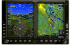
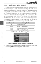
..., turn the large MFD knob to highlight the "Traffic" options. If the aircraft has a TAS unit installed, the GDU 620 will be configured for TAS. Sec 6 Symbols Sec 7 Appendix A Glossary Sec 8 Index Appendix B 3-32 Garmin G600 Pilot's Guide 190-00601-02 Rev. Coverage follows the airplane. Coverage is limited to customize the display...
..., turn the large MFD knob to highlight the "Traffic" options. If the aircraft has a TAS unit installed, the GDU 620 will be configured for TAS. Sec 6 Symbols Sec 7 Appendix A Glossary Sec 8 Index Appendix B 3-32 Garmin G600 Pilot's Guide 190-00601-02 Rev. Coverage follows the airplane. Coverage is limited to customize the display...

Pilots Guide
Page 104
...B Foreword System Sec 1 3.4 Aux Mode Pages The Aux mode provides pages for System Setup, XM Information (if installed), and system Status. 3.4.1 System Settings G600 system settings are restored by using the Page Menu options. The "Restore Unit Defaults" selection restores all default settings.... System Setup Page The default values set by the installer during installation are managed from the Aux Mode System Setup Page. The "Restore Airspeed Defaults" selection restores only the Airspeed Reference default settings. 3-46 Garmin G600 Pilot's Guide 190-00601-02 Rev. The following ...
...B Foreword System Sec 1 3.4 Aux Mode Pages The Aux mode provides pages for System Setup, XM Information (if installed), and system Status. 3.4.1 System Settings G600 system settings are restored by using the Page Menu options. The "Restore Unit Defaults" selection restores all default settings.... System Setup Page The default values set by the installer during installation are managed from the Aux Mode System Setup Page. The "Restore Airspeed Defaults" selection restores only the Airspeed Reference default settings. 3-46 Garmin G600 Pilot's Guide 190-00601-02 Rev. The following ...

Pilots Guide
Page 106
... the value is recycled, the values you set during installation. System Sec 1 PFD Sec 2 MFD Sec 3 Features Avoidance Hazard Sec 4 Additional Sec 5 & Alerts Annun. B Index Appendix B Default reference airspeeds are adjusted with this function. The next value will now be highlighted. 3-48 Garmin G600 Pilot's Guide 190-00601-02 Rev. A marker will appear...
... the value is recycled, the values you set during installation. System Sec 1 PFD Sec 2 MFD Sec 3 Features Avoidance Hazard Sec 4 Additional Sec 5 & Alerts Annun. B Index Appendix B Default reference airspeeds are adjusted with this function. The next value will now be highlighted. 3-48 Garmin G600 Pilot's Guide 190-00601-02 Rev. A marker will appear...

Pilots Guide
Page 107
... small MFD knob to the Barometric Setting on either GDU will change it on both units. B Garmin G600 Pilot's Guide 3-49 When Barometric Correction is synchronized, any changes to select "ON" or "OFF." 3) Press ENT. Foreword Sec 1 System Sec 2 PFD 3.4.1.3 Synchronization (Dual Installations Only) Dual GDU 620 units when connected in both GDUs.
... small MFD knob to the Barometric Setting on either GDU will change it on both units. B Garmin G600 Pilot's Guide 3-49 When Barometric Correction is synchronized, any changes to select "ON" or "OFF." 3) Press ENT. Foreword Sec 1 System Sec 2 PFD 3.4.1.3 Synchronization (Dual Installations Only) Dual GDU 620 units when connected in both GDUs.

Pilots Guide
Page 112
Foreword 3.4.2 XM Information (Optional) The Aux mode XM Information page displays information about the XM radios, service, and products when the GDL 69/69A is installed and the XM Radio service is activated. B Index Appendix B Sec 6 Symbols Sec 7 Appendix A Glossary Sec 8 Figure 3-70 XM Information 3-54 Garmin G600 Pilot's Guide 190-00601-02 Rev. System Sec 1 PFD Sec 2 MFD Sec 3 Features Avoidance Hazard Sec 4 Additional Sec 5 & Alerts Annun.
Foreword 3.4.2 XM Information (Optional) The Aux mode XM Information page displays information about the XM radios, service, and products when the GDL 69/69A is installed and the XM Radio service is activated. B Index Appendix B Sec 6 Symbols Sec 7 Appendix A Glossary Sec 8 Figure 3-70 XM Information 3-54 Garmin G600 Pilot's Guide 190-00601-02 Rev. System Sec 1 PFD Sec 2 MFD Sec 3 Features Avoidance Hazard Sec 4 Additional Sec 5 & Alerts Annun.

Pilots Guide
Page 113
... your remotely mounted GDL 69A. Based on the XM Satellite Radio display is available through the XM Satellite Radio Service when activated in the optional installation of the GDL 69A. B Garmin G600 Pilot's Guide 3-55 The information on signal from satellites, coverage far exceeds land-based transmissions.
... your remotely mounted GDL 69A. Based on the XM Satellite Radio display is available through the XM Satellite Radio Service when activated in the optional installation of the GDL 69A. B Garmin G600 Pilot's Guide 3-55 The information on signal from satellites, coverage far exceeds land-based transmissions.
Pilots Guide
Page 116
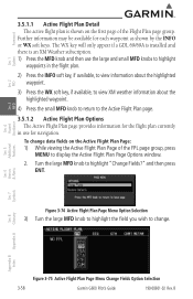
... FPL page group, press MENU to display the Active Flight Plan Page Options window. 2. The WX key will only appear if a GDL 69/69A is installed and there is shown on the Active Flight Plan Page: 1) While viewing the Active Flight Plan Page of the Flight Plan page group. Turn the... Sec 4 Additional Sec 5 & Alerts Annun. Sec 6 Symbols Sec 7 Appendix A Glossary Sec 8 Index Appendix B Figure 3-75 Active Flight Plan Page Menu Change Fields Option Selection 3-58 Garmin G600 Pilot's Guide 190-00601-02 Rev.
... FPL page group, press MENU to display the Active Flight Plan Page Options window. 2. The WX key will only appear if a GDL 69/69A is installed and there is shown on the Active Flight Plan Page: 1) While viewing the Active Flight Plan Page of the Flight Plan page group. Turn the... Sec 4 Additional Sec 5 & Alerts Annun. Sec 6 Symbols Sec 7 Appendix A Glossary Sec 8 Index Appendix B Figure 3-75 Active Flight Plan Page Menu Change Fields Option Selection 3-58 Garmin G600 Pilot's Guide 190-00601-02 Rev.

Pilots Guide
Page 119
.... Foreword 3.5.2.2 Waypoint Weather Detail (Optional) METAR and TAF text are displayed on the Waypoint Weather Information Page if the GDL 69/69A is installed and an XM weather subscription is the standard format for 24-hour weather forecasts. B Garmin G600 Pilot's Guide 3-61 Appendix B Index METAR data is displayed only in weather conditions.
.... Foreword 3.5.2.2 Waypoint Weather Detail (Optional) METAR and TAF text are displayed on the Waypoint Weather Information Page if the GDL 69/69A is installed and an XM weather subscription is the standard format for 24-hour weather forecasts. B Garmin G600 Pilot's Guide 3-61 Appendix B Index METAR data is displayed only in weather conditions.


