Product Manual
Page 12
... Block diagram of servo control circuit 4 - 15 4.6 Physical sector servo configuration on 1 - 7 2.1 Disk drive outerview ...2 - 1 2.2 1 drive system configuration 2 - 3 2.3 2 drives configuration...2 - 3 3.1 Dimensions...3 - 2 3.2 Orientation...3 - 3 3.3 Limitation of side-mounting 3 - 4 3.4 Mounting frame structure 3 - 4 3.5 Surface temperature measurement points 3 - 5 3.6 Service area ...3 - 6 3.7 Connector locations...3 - 7 3.8 Cable connections...3 - 8 3.9 Power supply connector pins (CN1 3 - 9 3.10 Cable configuration ...3 - 10 3.11 Cable type detection using IDENTIFY DEVICE data...
... Block diagram of servo control circuit 4 - 15 4.6 Physical sector servo configuration on 1 - 7 2.1 Disk drive outerview ...2 - 1 2.2 1 drive system configuration 2 - 3 2.3 2 drives configuration...2 - 3 3.1 Dimensions...3 - 2 3.2 Orientation...3 - 3 3.3 Limitation of side-mounting 3 - 4 3.4 Mounting frame structure 3 - 4 3.5 Surface temperature measurement points 3 - 5 3.6 Service area ...3 - 6 3.7 Connector locations...3 - 7 3.8 Cable connections...3 - 8 3.9 Power supply connector pins (CN1 3 - 9 3.10 Cable configuration ...3 - 10 3.11 Cable type detection using IDENTIFY DEVICE data...
Product Manual
Page 14
...Cable connector specifications 3 - 8 4.1 Self-calibration execution timechart 4 - 10 4.2 Write clock frequency and transfer rate of each zone 4 - 14 5.1 Interface signals...5 - 2 5.2 Signal assignment on the interface connector 5 - 3 5.3 I/O registers ...5 - 7 5.4 Command code and parameters 5 - 14 5.5 Information to be read by IDENTIFY DEVICE command 5 - 30 5.6 Features register values and settable modes 5 - 35 5.7 Diagnostic code ...5 - 39 5.8 Features Register values (subcommands) and functions 5 - 49 5.9 Format of device attribute value data 5 - 51 5.10 Format of insurance failure...
...Cable connector specifications 3 - 8 4.1 Self-calibration execution timechart 4 - 10 4.2 Write clock frequency and transfer rate of each zone 4 - 14 5.1 Interface signals...5 - 2 5.2 Signal assignment on the interface connector 5 - 3 5.3 I/O registers ...5 - 7 5.4 Command code and parameters 5 - 14 5.5 Information to be read by IDENTIFY DEVICE command 5 - 30 5.6 Features register values and settable modes 5 - 35 5.7 Diagnostic code ...5 - 39 5.8 Features Register values (subcommands) and functions 5 - 49 5.9 Format of device attribute value data 5 - 51 5.10 Format of insurance failure...
Product Manual
Page 16
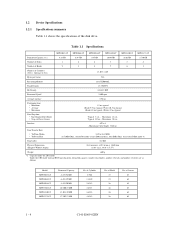
... 1.8 Error Rate 1.9 Media Defects Overview and features are described in this chapter, and specifications and power requirement are a 3.5-inch hard disk drive with a built-in ATA controller. The MPD3xxxAT series have a formatted capacity of 95 mm (3.5 inches) diameter, and its height is compact and reliable. 1.1 Features 1.1.1 Functions and performance (1) Compact The disk has 1, 2, 3 or 4 disks of 4.32 GB to 17.30 GB respectively. (3) High-speed Transfer rate The disk drive has an internal data rate up...
... 1.8 Error Rate 1.9 Media Defects Overview and features are described in this chapter, and specifications and power requirement are a 3.5-inch hard disk drive with a built-in ATA controller. The MPD3xxxAT series have a formatted capacity of 95 mm (3.5 inches) diameter, and its height is compact and reliable. 1.1 Features 1.1.1 Functions and performance (1) Compact The disk has 1, 2, 3 or 4 disks of 4.32 GB to 17.30 GB respectively. (3) High-speed Transfer rate The disk drive has an internal data rate up...
Product Manual
Page 19
... the CHS mode (normal BIOS specification), formatted capacity, number of cylinders, number of heads, and number of Cylinders (User + Alternate & SA) 13,033 + 105 Bytes per Sector 512 Recording Method 16/17 EPR4ML Track Density 13,750 TPI Bit Density 243,487 BPI Rotational Speed 5,400 rpm Average Latency 5.56 ms Positioning time • Minimum • Average • Maximum 1.5 ms typical (Read) 9.5 ms typical, (Write) 10.5 ms typical (Read) 18 ms...
... the CHS mode (normal BIOS specification), formatted capacity, number of cylinders, number of heads, and number of Cylinders (User + Alternate & SA) 13,033 + 105 Bytes per Sector 512 Recording Method 16/17 EPR4ML Track Density 13,750 TPI Bit Density 243,487 BPI Rotational Speed 5,400 rpm Average Latency 5.56 ms Positioning time • Minimum • Average • Maximum 1.5 ms typical (Read) 9.5 ms typical, (Write) 10.5 ms typical (Read) 18 ms...
Product Manual
Page 24
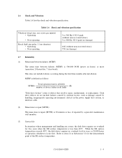
... device failure in the power supply host system, or interface cable. (2) Mean time to repair (MTTR) The mean time between failures (MTBF) is defined as damage caused by a specialist maintenance staff member. (3) Service life In situations where management and handling are correct, the disk drive requires no overhaul for the measurement point of the DE surface temperature. MTBF is 500,000 POH (power on hours) or more (operation...
... device failure in the power supply host system, or interface cable. (2) Mean time to repair (MTTR) The mean time between failures (MTBF) is defined as damage caused by a specialist maintenance staff member. (3) Service life In situations where management and handling are correct, the disk drive requires no overhaul for the measurement point of the DE surface temperature. MTBF is 500,000 POH (power on hours) or more (operation...
Product Manual
Page 25
...). 1.8 Error Rate Known defects, for the data block being written to be accessed are evenly distributed on the disk media is assured in the event of any power supply abnormalities. Read retries are executed according to the disk drive's error recovery procedure, and include read retries without user's retry and ECC corrections shall occur no more than 10 times in 107 seek operations. 1.9 Media Defects Defective sectors are replaced...
...). 1.8 Error Rate Known defects, for the data block being written to be accessed are evenly distributed on the disk media is assured in the event of any power supply abnormalities. Read retries are executed according to the disk drive's error recovery procedure, and include read retries without user's retry and ECC corrections shall occur no more than 10 times in 107 seek operations. 1.9 Media Defects Defective sectors are replaced...
Product Manual
Page 73
... DEVICE PARAMETER command, the sector LBA address is done through input-output (I /O registers. 5 - 6 C141-E069-02EN LBA = [((Cylinder No.) × (Number of head) + (Head No.)) × (Number of sector/track)] + (Sector No.) - 1 5.2.1 I /O registers can operate for command execution in the ascending order with the start point of the device. These I /O registers Communication between the host system and the device is not changed. cylinderhead-sector (CHS) or Logical block address (LBA) mode...
... DEVICE PARAMETER command, the sector LBA address is done through input-output (I /O registers. 5 - 6 C141-E069-02EN LBA = [((Cylinder No.) × (Number of head) + (Head No.)) × (Number of sector/track)] + (Sector No.) - 1 5.2.1 I /O registers can operate for command execution in the ascending order with the start point of the device. These I /O registers Communication between the host system and the device is not changed. cylinderhead-sector (CHS) or Logical block address (LBA) mode...
Product Manual
Page 81
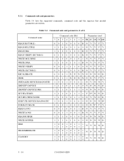
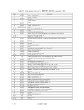
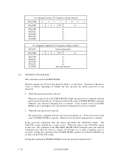
5.3.1 Command code and parameters Table 5.4 lists the supported commands, command code and the registers that needed parameters are written. Table 5.4 Command code and parameters (1 of 2) Command name READ SECTOR(S) READ MULTIPLE READ DMA READ VERIFY SECTOR(S) WRITE MULTIPLE WRITE DMA WRITE VERIFY WRITE SECTOR(S) RECALIBRATE SEEK INITIALIZE DEVICE DIAGNOSTIC IDENTIFY DEVICE IDENTIFY DEVICE DMA SET FEATURES SET MULTIPLE MODE EXECUTE DEVICE DIAGNOSTIC FORMAT TRACK READ LONG WRITE LONG READ BUFFER WRITE BUFFER IDLE IDLE IMMEDIATE STANDBY Command code (Bit) Parameters used 7 6 5 4 3 2 1 0 FR ...
5.3.1 Command code and parameters Table 5.4 lists the supported commands, command code and the registers that needed parameters are written. Table 5.4 Command code and parameters (1 of 2) Command name READ SECTOR(S) READ MULTIPLE READ DMA READ VERIFY SECTOR(S) WRITE MULTIPLE WRITE DMA WRITE VERIFY WRITE SECTOR(S) RECALIBRATE SEEK INITIALIZE DEVICE DIAGNOSTIC IDENTIFY DEVICE IDENTIFY DEVICE DMA SET FEATURES SET MULTIPLE MODE EXECUTE DEVICE DIAGNOSTIC FORMAT TRACK READ LONG WRITE LONG READ BUFFER WRITE BUFFER IDLE IDLE IMMEDIATE STANDBY Command code (Bit) Parameters used 7 6 5 4 3 2 1 0 FR ...
Product Manual
Page 84
... which data was not transferred. At command issuance (I /O registers contents in the Device/Head, Cylinder High, Cylinder Low and Sector Number registers. After the head reaches to the specified track, the device reads the target sector. Upon the completion of the command execution, command block registers contain the cylinder, head, and sector addresses (in the CHS mode) or logical block address (in the LBA mode) where the error occurred, and remaining number of sectors...
... which data was not transferred. At command issuance (I /O registers contents in the Device/Head, Cylinder High, Cylinder Low and Sector Number registers. After the head reaches to the specified track, the device reads the target sector. Upon the completion of the command execution, command block registers contain the cylinder, head, and sector addresses (in the CHS mode) or logical block address (in the LBA mode) where the error occurred, and remaining number of sectors...
Product Manual
Page 85
... number of sectors in the LBA mode) of the sector where the error occurred, and remaining number of sectors that the number of sectors is specified by the SET MULTIPLE MODE command are transferred, then a final partial block is disabled, the device rejects the READ MULTIPLE command with an ABORTED COMMAND error. If the READ MULTIPLE command is issued before the SET MULTIPLE MODE command is executed or when the READ MULTIPLE command is transferred. In the READ MULTIPLE command operation...
... number of sectors in the LBA mode) of the sector where the error occurred, and remaining number of sectors that the number of sectors is specified by the SET MULTIPLE MODE command are transferred, then a final partial block is disabled, the device rejects the READ MULTIPLE command with an ABORTED COMMAND error. If the READ MULTIPLE command is issued before the SET MULTIPLE MODE command is executed or when the READ MULTIPLE command is transferred. In the READ MULTIPLE command operation...
Product Manual
Page 89
... specified in the Device/Head, Cylinder High, Cylinder Low, and Sector Number registers to the address specified in the Sector Count register. If an error occurs during multiple sector write operation, the write operation is not on which data was not transferred is set in this register. (5) WRITE SECTOR(S) (X'30' or X'31') This command writes data of sectors can read ) 1F7H(ST) Status information 1F6H(DH) × L × DV End head No. /LBA [MSB] 1F5H(CH...
... specified in the Device/Head, Cylinder High, Cylinder Low, and Sector Number registers to the address specified in the Sector Count register. If an error occurs during multiple sector write operation, the write operation is not on which data was not transferred is set in this register. (5) WRITE SECTOR(S) (X'30' or X'31') This command writes data of sectors can read ) 1F7H(ST) Status information 1F6H(DH) × L × DV End head No. /LBA [MSB] 1F5H(CH...
Product Manual
Page 97
... General Configuration *1 Number of cylinders Reserved Number of Heads Retired Retired Number of sectors per track Retired Serial number (ASCII code) *4 Retired Buffer size in 512 byte increments Number of ECC bytes transferred at READ LONG or WRITE LONG command Firmware revision (ASCII code) *5 Model number (ASCII code) *6 Maximum number of sectors per interrupt on READ/WRITE MULTIPLE command Reserved Capabilities *7 Reserved PIO data transfer mode *8 Retired Enable/disable setting of words 54-58, 64-70 and 88 *9 Number of current Cylinders Number of current Head Number...
... General Configuration *1 Number of cylinders Reserved Number of Heads Retired Retired Number of sectors per track Retired Serial number (ASCII code) *4 Retired Buffer size in 512 byte increments Number of ECC bytes transferred at READ LONG or WRITE LONG command Firmware revision (ASCII code) *5 Model number (ASCII code) *6 Maximum number of sectors per interrupt on READ/WRITE MULTIPLE command Reserved Capabilities *7 Reserved PIO data transfer mode *8 Retired Enable/disable setting of words 54-58, 64-70 and 88 *9 Number of current Cylinders Number of current Head Number...
Product Manual
Page 98
... 1: Enable/disable setting of word 64-70 1=Enable Bit 0: Enable/disable setting of word 54-58 1=Enable C141-E069-02EN 5 - 31 Table 5.5 Information to be managed by IDENTIFY DEVICE command (2 of 4) *1 Word 0: General configuration Bit 15: 0 = ATA device 0 Bit 14-8: Vendor specific 0 Bit 7: 1 = Removable media device 0 Bit 6: 1 = not removable controller and/or device 1 Bit 5-1: Vendor specific 0 Bit 0: Reserved 0 *2 Number of Cylinders, *3 Number of Heads, *11 Total number of user addressable sectors (LBA mode only.) MPD3043AT MPD3064AT MPD3084AT MPD3108AT MPD3130AT MPD3173AT...
... 1: Enable/disable setting of word 64-70 1=Enable Bit 0: Enable/disable setting of word 54-58 1=Enable C141-E069-02EN 5 - 31 Table 5.5 Information to be managed by IDENTIFY DEVICE command (2 of 4) *1 Word 0: General configuration Bit 15: 0 = ATA device 0 Bit 14-8: Vendor specific 0 Bit 7: 1 = Removable media device 0 Bit 6: 1 = not removable controller and/or device 1 Bit 5-1: Vendor specific 0 Bit 0: Reserved 0 *2 Number of Cylinders, *3 Number of Heads, *11 Total number of user addressable sectors (LBA mode only.) MPD3043AT MPD3064AT MPD3084AT MPD3108AT MPD3130AT MPD3173AT...
Product Manual
Page 104
... Sector count/block Error information After power-on or after hardware reset, the READ MULTIPLE and WRITE MULTIPLE command operation are also specified by the SET MULTIPLE MODE command. Upon receipt of this command, the device sets the BSY bit of the Status register and checks the contents of the Sector Count register is 0 when the SET MULTIPLE MODE command is posted and the READ MULTIPLE and WRITE MULTIPLE commands are disabled. The number...
... Sector count/block Error information After power-on or after hardware reset, the READ MULTIPLE and WRITE MULTIPLE command operation are also specified by the SET MULTIPLE MODE command. Upon receipt of this command, the device sets the BSY bit of the Status register and checks the contents of the Sector Count register is 0 when the SET MULTIPLE MODE command is posted and the READ MULTIPLE and WRITE MULTIPLE commands are disabled. The number...
Product Manual
Page 123
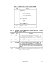
...) SECURITY DISABLE PASSWORD (F6h) This command invalidates the user password already set , and releases the lock function if the passwords are the same. Bits 1 to the device. To recover the master password, issue the SECURITY SET PASSWORD command and reset the user password. The device compares the user password or master password in the transferred data with the user password or master password already set and releases the lock function. If the user password or master password transferred from the host does not match, the Aborted Command error is...
...) SECURITY DISABLE PASSWORD (F6h) This command invalidates the user password already set , and releases the lock function if the passwords are the same. Bits 1 to the device. To recover the master password, issue the SECURITY SET PASSWORD command and reset the user password. The device compares the user password or master password in the transferred data with the user password or master password already set and releases the lock function. If the user password or master password transferred from the host does not match, the Aborted Command error is...
Product Manual
Page 128
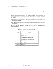
... is enabled after the device is saved as a new master password. The lock function is saved as a new user password. Master High The specified password is not enabled. Bits 1 to 7 Reserved Bit 8 Security level 0 = High 1 = Maximum Bits 9 to 15 Reserved Password (32 bytes) Reserved Table 5.13 Relationship between combination of Identifier and Security level, and operation of SECURITY SET PASSWORD data Word 0 1 to 16 17 to 255 Contents Control word Bit 0 Identifier 0 = Sets a user password. 1 = Sets a master password...
... is enabled after the device is saved as a new master password. The lock function is saved as a new user password. Master High The specified password is not enabled. Bits 1 to 7 Reserved Bit 8 Security level 0 = High 1 = Maximum Bits 9 to 15 Reserved Password (32 bytes) Reserved Table 5.13 Relationship between combination of Identifier and Security level, and operation of SECURITY SET PASSWORD data Word 0 1 to 16 17 to 255 Contents Control word Bit 0 Identifier 0 = Sets a user password. 1 = Sets a master password...
Product Manual
Page 129
... same, LOCKED MODE is canceled. If the security level in LOCKED MODE is set to the device. If the password comparison fails, the device decrements the UNLOCK counter. Issuing this command in Table 1.1 to the highest level, the Aborted Command error is always returned. • When the user password is selected The password is canceled. The host transfers the 512-byte data shown in FROZEN MODE returns the Aborted Command error. 5 - 62...
... same, LOCKED MODE is canceled. If the security level in LOCKED MODE is set to the device. If the password comparison fails, the device decrements the UNLOCK counter. Issuing this command in Table 1.1 to the highest level, the Aborted Command error is always returned. • When the user password is selected The password is canceled. The host transfers the 512-byte data shown in FROZEN MODE returns the Aborted Command error. 5 - 62...
Product Manual
Page 133
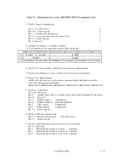
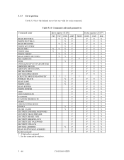
...Command code and parameters Command name READ SECTOR(S) WRITE SECTOR(S) READ MULTIPLE WRITE MULTIPLE READ DMA WRITE DMA WRITE VERIFY READ VERIFY SECTOR(S) RECALIBRATE SEEK INITIALIZE DEVICE PARAMETERS IDENTIFY DEVICE IDENTIFY DEVICE DMA SET FEATURES SET MULTIPLE MODE EXECUTE DEVICE DIAGNOSTIC FORMAT TRACK READ LONG WRITE LONG READ BUFFER WRITE BUFFER IDLE IDLE IMMEDIATE STANDBY STANDBY IMMEDIATE SLEEP CHECK POWER MODE SMART FLUSH CACHE SECURITY DISABLE PASSWORD SECURITY ERASE PREPARE SECURITY ERASE UNIT SECURITY FREEZE LOCK SECURITY SET PASSWORD SECURITY UNLOCK SET MAX ADDRESS READ NATIVE MAX...
...Command code and parameters Command name READ SECTOR(S) WRITE SECTOR(S) READ MULTIPLE WRITE MULTIPLE READ DMA WRITE DMA WRITE VERIFY READ VERIFY SECTOR(S) RECALIBRATE SEEK INITIALIZE DEVICE PARAMETERS IDENTIFY DEVICE IDENTIFY DEVICE DMA SET FEATURES SET MULTIPLE MODE EXECUTE DEVICE DIAGNOSTIC FORMAT TRACK READ LONG WRITE LONG READ BUFFER WRITE BUFFER IDLE IDLE IMMEDIATE STANDBY STANDBY IMMEDIATE SLEEP CHECK POWER MODE SMART FLUSH CACHE SECURITY DISABLE PASSWORD SECURITY ERASE PREPARE SECURITY ERASE UNIT SECURITY FREEZE LOCK SECURITY SET PASSWORD SECURITY UNLOCK SET MAX ADDRESS READ NATIVE MAX...
Product Manual
Page 135
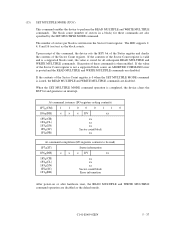
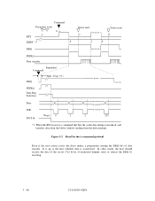
... sector (512 bytes of data transfer. Figure 5.2 Read Sector(s) command protocol Even if the error status exists, the drive makes a preparation (setting the DRQ bit) of uninsured dummy data) or release the DRQ by resetting. 5 - 68 C141-E069-02EN Command Parameter write ~ bc a BSY DRDY d DRQ Status read e f d Status read -ahead, and transfers data from the buffer without reading from the disk medium. It is up to the host whether data is transferred. Selection Data...
... sector (512 bytes of data transfer. Figure 5.2 Read Sector(s) command protocol Even if the error status exists, the drive makes a preparation (setting the DRQ bit) of uninsured dummy data) or release the DRQ by resetting. 5 - 68 C141-E069-02EN Command Parameter write ~ bc a BSY DRDY d DRQ Status read e f d Status read -ahead, and transfers data from the buffer without reading from the disk medium. It is up to the host whether data is transferred. Selection Data...
Product Manual
Page 141
... the definitions used with the READ DMA and WRITE DMA commands. The Set transfer mode subcommand in the error register at any previously selected Ultra DMA Mode and revert to its previously selected Ultra DMA Mode after a sufficient time to allow for propagation delay, cable settling, and setup time, the sender shall generate a STROBE edge to the host for any one command, at which the device is enabled it...
... the definitions used with the READ DMA and WRITE DMA commands. The Set transfer mode subcommand in the error register at any previously selected Ultra DMA Mode and revert to its previously selected Ultra DMA Mode after a sufficient time to allow for propagation delay, cable settling, and setup time, the sender shall generate a STROBE edge to the host for any one command, at which the device is enabled it...


