Manual/User Guide
Page 2
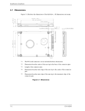
All dimensions are in mm. *1 The PCA and connectors are not included in these dimensions. *2 Dimension from the center of the user tap to the base of the connector pins *3 Length of the connector pins *4 Dimension from the outer edge of the user tap to the center of the connector pins *5 Dimension from the outer edge of the user tap to the innermost edge of the disk drive. Installation Conditions 3.1 Dimensions Figure 3.1 illustrates the dimensions of the connector pins Figure 3.1 Dimensions 3-2 C141-E245
All dimensions are in mm. *1 The PCA and connectors are not included in these dimensions. *2 Dimension from the center of the user tap to the base of the connector pins *3 Length of the connector pins *4 Dimension from the outer edge of the user tap to the center of the connector pins *5 Dimension from the outer edge of the user tap to the innermost edge of the disk drive. Installation Conditions 3.1 Dimensions Figure 3.1 illustrates the dimensions of the connector pins Figure 3.1 Dimensions 3-2 C141-E245
Manual/User Guide
Page 9
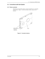
SATA interface PCA and power connectors Figure 3.7 Connector locations C141-E245 3-9 3.3 Connections with Host System 3.3 Connections with Host System 3.3.1 Device connector The disk drive has the SATA interface connectors listed below for connecting external devices. Figure 3.7 shows the locations of these connectors and terminals.
SATA interface PCA and power connectors Figure 3.7 Connector locations C141-E245 3-9 3.3 Connections with Host System 3.3 Connections with Host System 3.3.1 Device connector The disk drive has the SATA interface connectors listed below for connecting external devices. Figure 3.7 shows the locations of these connectors and terminals.
Manual/User Guide
Page 10
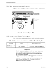
...guaranteed. The connection reliability per number of insertion/extractions varies with the condition of the SATA interface connector and pin numbers. Power supply segment Signal segment View from the connector side S1 pins in the signal P1 pins in the power segment supply segment View... from the several choices including its mating with the host system. Table 3.2 The recommended connector specifications for the host system Segment SATA interface and power supply Name Host receptacle Model (Manufacturer) 67492-0220 (Molex) or compatibles IMPORTANT The above...
...guaranteed. The connection reliability per number of insertion/extractions varies with the condition of the SATA interface connector and pin numbers. Power supply segment Signal segment View from the connector side S1 pins in the signal P1 pins in the power segment supply segment View... from the several choices including its mating with the host system. Table 3.2 The recommended connector specifications for the host system Segment SATA interface and power supply Name Host receptacle Model (Manufacturer) 67492-0220 (Molex) or compatibles IMPORTANT The above...
Manual/User Guide
Page 11
... cable connection Take note of the following precaution about plugging a SATA interface cable into the SATA interface connector of the disk drive and plugging the connector into a host receptacle: When plugging together the disk drive SATA interface connector and the host receptacle or SATA interface cable connector, do not apply more than 10 kgf of force in the connection direction...
... cable connection Take note of the following precaution about plugging a SATA interface cable into the SATA interface connector of the disk drive and plugging the connector into a host receptacle: When plugging together the disk drive SATA interface connector and the host receptacle or SATA interface cable connector, do not apply more than 10 kgf of force in the connection direction...