
Manual/User Guide
Page 2
...not intended for special uses (atomic controls, aeronautic or space systems, mass transport vehicle operating controls, medical devices for life support, or weapons firing controls) where particularly high reliability requirements exist, where the pertinent levels of safety are requested to as office..., or any product or system in standard applications such as "mission-critical" use). All Rights Reserved, Copyright FUJITSU LIMITED 2003 Read thoroughly before embarking on such specialized use of any other cause. Customers considering the use in accordance with respect...
...not intended for special uses (atomic controls, aeronautic or space systems, mass transport vehicle operating controls, medical devices for life support, or weapons firing controls) where particularly high reliability requirements exist, where the pertinent levels of safety are requested to as office..., or any product or system in standard applications such as "mission-critical" use). All Rights Reserved, Copyright FUJITSU LIMITED 2003 Read thoroughly before embarking on such specialized use of any other cause. Customers considering the use in accordance with respect...

Manual/User Guide
Page 22
.... (4) High resistance against non-operation shock up to 8820 m/s2 (900G). 1-2 C141-E192-02EN The disk drive supports an external data rate up to 41.3 MB/s. The disk drive has a formatted capacity of 80 GB (MHT2080AT), 60 GB (MHT2060AT), 40 GB (MHT2040AT), 30 GB (MHT2030AT) and 20 GB (MHT2020AT) respectively. (3) High-speed Transfer...
.... (4) High resistance against non-operation shock up to 8820 m/s2 (900G). 1-2 C141-E192-02EN The disk drive supports an external data rate up to 41.3 MB/s. The disk drive has a formatted capacity of 80 GB (MHT2080AT), 60 GB (MHT2060AT), 40 GB (MHT2040AT), 30 GB (MHT2030AT) and 20 GB (MHT2020AT) respectively. (3) High-speed Transfer...
Manual/User Guide
Page 31
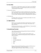
...; STANDBY • STANDBY IMMEDIATE • SLEEP • IDLE Emergency Unload other than 10 times when reading data of 1014 bits. The product supports a minimum of 20,000 times. Thus, the hosts see a defect-free devices. The user need not be concerned with alternates when the disk...by maximum read retries accompanying head offset operations. (2) Positioning error Positioning (seek) errors that loads the head on the disk. The product supports the Emergency Unload a minimum of 300,000 normal Load/Unload cycles. It is formatted prior to the disk drive's error recovery procedure, ...
...; STANDBY • STANDBY IMMEDIATE • SLEEP • IDLE Emergency Unload other than 10 times when reading data of 1014 bits. The product supports a minimum of 20,000 times. Thus, the hosts see a defect-free devices. The user need not be concerned with alternates when the disk...by maximum read retries accompanying head offset operations. (2) Positioning error Positioning (seek) errors that loads the head on the disk. The product supports the Emergency Unload a minimum of 300,000 normal Load/Unload cycles. It is formatted prior to the disk drive's error recovery procedure, ...
Manual/User Guide
Page 37
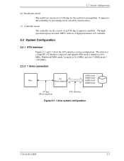
... 44pin PC AT interface connector and supports PIO mode 4 transfer at 16.6 MB/s, Multiword DMA mode 2 transfer at 16.6 MB/s and also U-DMA mode 5 (100 MB/s). 2.2.2 1 drive connection MHT2080AT MMHHTC22006302AATT MMHHTC22004400AATT MHT2030AT Figure 2.2 1 drive... system configuration C141-E192-02EN 2-3 The highspeed microprocessor unit (MPU) achieves a high-performance AT controller. 2.2 System Configuration 2.2.1 ATA interface Figures 2.2 and 2.3 show the ATA interface system configuration. It...
... 44pin PC AT interface connector and supports PIO mode 4 transfer at 16.6 MB/s, Multiword DMA mode 2 transfer at 16.6 MB/s and also U-DMA mode 5 (100 MB/s). 2.2.2 1 drive connection MHT2080AT MMHHTC22006302AATT MMHHTC22004400AATT MHT2030AT Figure 2.2 1 drive... system configuration C141-E192-02EN 2-3 The highspeed microprocessor unit (MPU) achieves a high-performance AT controller. 2.2 System Configuration 2.2.1 ATA interface Figures 2.2 and 2.3 show the ATA interface system configuration. It...
Manual/User Guide
Page 80
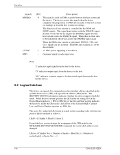
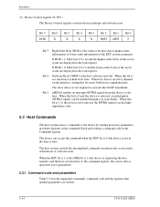
... host system (at reading) or from the host system (at each signal wire. Grounded signal at writing). The IDENTIFY DEVICE information indicates whether the device supports the LBA mode. LBA = [((Cylinder No.) × (Number of head) + (Head No.)) × (Number of the Cylinder High, Cylinder Low, and Sector Number registers are...
... host system (at reading) or from the host system (at each signal wire. Grounded signal at writing). The IDENTIFY DEVICE information indicates whether the device supports the LBA mode. LBA = [((Cylinder No.) × (Number of head) + (Head No.)) × (Number of the Cylinder High, Cylinder Low, and Sector Number registers are...
Manual/User Guide
Page 88
... the BSY bit is 0 (the device is the host software reset bit. The slave device is not guaranteed. 5.3.1 Command code and parameters Table 5.3 lists the supported commands, command code and the registers that selects higher-order information or lower-order information of hardware or software reset. The host system can be...
... the BSY bit is 0 (the device is the host software reset bit. The slave device is not guaranteed. 5.3.1 Command code and parameters Table 5.3 lists the supported commands, command code and the registers that selects higher-order information or lower-order information of hardware or software reset. The host system can be...
Manual/User Guide
Page 108
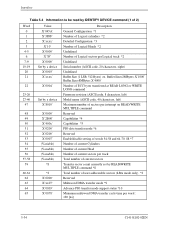
... Table 5.4 Information to be read by IDENTIFY DEVICE command (1 of user addressable sectors (LBA mode only) *2 Reserved Multiword DMA transfer mode *9 Advance PIO transfer mode support status *10 Minimum multiword DMA transfer cycle time per Logical track *2 Undefined Serial number (ASCII code, 20 characters, right) Undefined Buffer Size (1 LSB: 512 Bytes...
... Table 5.4 Information to be read by IDENTIFY DEVICE command (1 of user addressable sectors (LBA mode only) *2 Reserved Multiword DMA transfer mode *9 Advance PIO transfer mode support status *10 Minimum multiword DMA transfer cycle time per Logical track *2 Undefined Serial number (ASCII code, 20 characters, right) Undefined Buffer Size (1 LSB: 512 Bytes...
Manual/User Guide
Page 109
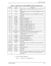
... Table 5.4 Information to be read by IDENTIFY DEVICE command (2 of 2) Word 66 67 68 69-79 80 81 82 83 84 85 86 87 88 89 90 91 92 93 94 95-99 100-103 104-... command sets *12 Support of command sets *13 Support of command sets/function *14 Valid of command sets/function *15 Valid of command sets/function *16 Default of command sets/function *17 Ultra DMA transfer mode *18 Security Erase Unit execution time (1 LSB: 2 min.) *19 Enhanced Security...bits 7 to 0 of word 0 to 254 and word 255, in byte units.) *1 Word 0: General configuration Bit 15: ATA device = 0, ATAPI device = 1 C141-E192-02EN 5-35
... Table 5.4 Information to be read by IDENTIFY DEVICE command (2 of 2) Word 66 67 68 69-79 80 81 82 83 84 85 86 87 88 89 90 91 92 93 94 95-99 100-103 104-... command sets *12 Support of command sets *13 Support of command sets/function *14 Valid of command sets/function *15 Valid of command sets/function *16 Default of command sets/function *17 Ultra DMA transfer mode *18 Security Erase Unit execution time (1 LSB: 2 min.) *19 Enhanced Security...bits 7 to 0 of word 0 to 254 and word 255, in byte units.) *1 Word 0: General configuration Bit 15: ATA device = 0, ATAPI device = 1 C141-E192-02EN 5-35
Manual/User Guide
Page 110
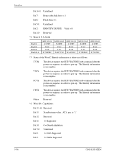
... Reserved Bit 11: 1 = Supported Bit 10: 0 = Disable inhibition Bit 7-0: Undefined Bit 8: 1 = LBA Supported Bit 9: 1 = DMA Supported 5-36 C141-E192-02EN The Identify...device requires the SET FEATURES sub-command after the power-on sequence in order to spin-up . ATA spec is '1.' Interface Bit 14-8: Undefined Bit 7: Removable disk drive = 1 Bit 6: Fixed... Bit 2: IDENTIFY DEVICE Valid = 0 Bit 1-0: Reserved *2 Word 1, 3, 6, 60-61 Word 01 Word 03 Word 06 Word 60-61 MHT2080AT X'3FFF' X'10' X'3F' X'950F8B0' MHT2060AT X'3FFF' X'10' X'3F' X'6FC7C80' MHT2040AT X'3FFF' X'10' X'3F' X'4A85300'...
... Reserved Bit 11: 1 = Supported Bit 10: 0 = Disable inhibition Bit 7-0: Undefined Bit 8: 1 = LBA Supported Bit 9: 1 = DMA Supported 5-36 C141-E192-02EN The Identify...device requires the SET FEATURES sub-command after the power-on sequence in order to spin-up . ATA spec is '1.' Interface Bit 14-8: Undefined Bit 7: Removable disk drive = 1 Bit 6: Fixed... Bit 2: IDENTIFY DEVICE Valid = 0 Bit 1-0: Reserved *2 Word 1, 3, 6, 60-61 Word 01 Word 03 Word 06 Word 60-61 MHT2080AT X'3FFF' X'10' X'3F' X'950F8B0' MHT2060AT X'3FFF' X'10' X'3F' X'6FC7C80' MHT2040AT X'3FFF' X'10' X'3F' X'4A85300'...

Manual/User Guide
Page 111
... Reserved Bit 8: 1 = Enable the multiple sector transfer Bit 7-0: Transfer sector count currently set by READ/WRITE MULTIPLE command without interrupt supports 2, 4, 8 and 16 sectors. *9 Word 63: Multiword DMA transfer mode Bit 15-11: Reserved Bit 10: '1' = multiword...0 is selected. Bit 7-3: Reserved Bit 2: 1 = Multiword DMA mode 2, 1, and 0 supported (Bit 1 = 0 = '1') Bit 1: 1 = Multiword DMA mode 1, and 0 supported (Bit 0 = '1') Bit 0: 1 = Mode 0 *10 Word 64: Advance PIO transfer mode support status Bit 15-8: Reserved C141-E192-02EN 5-37 Bit 9: '1' = multiword DMA mode 1 is...
... Reserved Bit 8: 1 = Enable the multiple sector transfer Bit 7-0: Transfer sector count currently set by READ/WRITE MULTIPLE command without interrupt supports 2, 4, 8 and 16 sectors. *9 Word 63: Multiword DMA transfer mode Bit 15-11: Reserved Bit 10: '1' = multiword...0 is selected. Bit 7-3: Reserved Bit 2: 1 = Multiword DMA mode 2, 1, and 0 supported (Bit 1 = 0 = '1') Bit 1: 1 = Multiword DMA mode 1, and 0 supported (Bit 0 = '1') Bit 0: 1 = Mode 0 *10 Word 64: Advance PIO transfer mode support status Bit 15-8: Reserved C141-E192-02EN 5-37 Bit 9: '1' = multiword DMA mode 1 is...
Manual/User Guide
Page 112
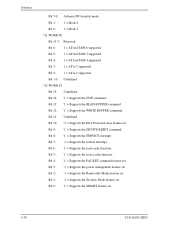
... Protected Area feature set . Bit 6: '1' = Supports the read cache function. Bit 1: '1' = Supports the Security Mode feature set . Bit 12: '1' = Supports the WRITE BUFFER command. Interface Bit 7-0: Advance PIO transfer mode Bit 1: 1 = Mode 4 Bit 0: 1 = Mode 3 *11 WORD 80 Bit 15-7: Reserved Bit 6: 1 = ATA/ATAPI-6 supported Bit 5: 1 = ATA/ATAPI-5 supported Bit 4: 1 = ATA/ATAPI-4 supported Bit 3: 1 = ATA-3 supported Bit 2: 1 = ATA-2 supported Bit 1-0: Undefined *12 WORD 82 Bit...
... Protected Area feature set . Bit 6: '1' = Supports the read cache function. Bit 1: '1' = Supports the Security Mode feature set . Bit 12: '1' = Supports the WRITE BUFFER command. Interface Bit 7-0: Advance PIO transfer mode Bit 1: 1 = Mode 4 Bit 0: 1 = Mode 3 *11 WORD 80 Bit 15-7: Reserved Bit 6: 1 = ATA/ATAPI-6 supported Bit 5: 1 = ATA/ATAPI-5 supported Bit 4: 1 = ATA/ATAPI-4 supported Bit 3: 1 = ATA-3 supported Bit 2: 1 = ATA-2 supported Bit 1-0: Undefined *12 WORD 82 Bit...

Manual/User Guide
Page 113
... is turned on, spin is started by the SET FEATURES sub-command. Bit 11: '1' = Device Configuration Overlay feature set . Bit 8: '1' = Supports the SET MAX Security extending command. Bit 3: '1' = Supports the Advanced Power Management feature set . Bit 2: '1' = Supports the CFA (Compact Flash Association) feature set . Bit 10:* '1' = 48 bit LBA feature set . Bit 12...
... is turned on, spin is started by the SET FEATURES sub-command. Bit 11: '1' = Device Configuration Overlay feature set . Bit 8: '1' = Supports the SET MAX Security extending command. Bit 3: '1' = Supports the Advanced Power Management feature set . Bit 2: '1' = Supports the CFA (Compact Flash Association) feature set . Bit 10:* '1' = 48 bit LBA feature set . Bit 12...
Manual/User Guide
Page 114
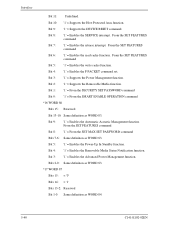
...cache function. Bit 5: '1' = Enables the Power-Up In Standby function. Bit 9: '1' = Enables the Automatic Acoustic Management function. Bit 3: '1' = Supports the Power Management function. Bit 1: '1' = From the SECURITY SET PASSWORD command Bit 0: '1' = From the SMART ENABLE OPERATION command *16 WORD 86 ...Bits 15: Reserved Bit 13-10: Same definition as WORD 83. Bit 2: '1' = Supports the Removable Media function. From the SET FEATURES command Bit 7: '1' = Enables the release interrupt. Bits 2-0: Same definition as WORD 83...
...cache function. Bit 5: '1' = Enables the Power-Up In Standby function. Bit 9: '1' = Enables the Automatic Acoustic Management function. Bit 3: '1' = Supports the Power Management function. Bit 1: '1' = From the SECURITY SET PASSWORD command Bit 0: '1' = From the SMART ENABLE OPERATION command *16 WORD 86 ...Bits 15: Reserved Bit 13-10: Same definition as WORD 83. Bit 2: '1' = Supports the Removable Media function. From the SET FEATURES command Bit 7: '1' = Enables the release interrupt. Bits 2-0: Same definition as WORD 83...
Manual/User Guide
Page 115
... 11: '1' = Device asserts PDIAG-. Bit 10, 9: Method for deciding the device No. Bit 7-0: Supportable Ultra DMA transfer mode Bit 5: '1' = Supports the Mode 5 Bit 4: '1' = Supports the Mode 4 Bit 3: '1' = Supports the Mode 3 Bit 2: '1' = Supports the Mode 2 Bit 1: '1' = Supports the Mode 1 Bit 0: '1' = Supports the Mode 0 *19 WORD 89 MHT2080AT = X'28': 80 minutes MHT2060AT = X'1E': 60 minutes MHT2040AT = X'14': 40 minutes MHT2030AT = X'0F': 30...
... 11: '1' = Device asserts PDIAG-. Bit 10, 9: Method for deciding the device No. Bit 7-0: Supportable Ultra DMA transfer mode Bit 5: '1' = Supports the Mode 5 Bit 4: '1' = Supports the Mode 4 Bit 3: '1' = Supports the Mode 3 Bit 2: '1' = Supports the Mode 2 Bit 1: '1' = Supports the Mode 1 Bit 0: '1' = Supports the Mode 0 *19 WORD 89 MHT2080AT = X'28': 80 minutes MHT2060AT = X'1E': 60 minutes MHT2040AT = X'14': 40 minutes MHT2030AT = X'0F': 30...

Manual/User Guide
Page 116
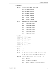
...- Bit 4: '1' = Device 0, assertion of device 0) *21 WORD 94 Bit 15-8: X'FE' Recommended acoustic management value. of DASP- FE-C0: Performance mode BF-80: Acoustic mode 00: Acoustic management is unused it. (It is same as "FE-CO") *22 WORD 100-103 When "48 bit LBA" of the option... (customize) is supported, same number of Device 0 (master drive), a valid value is set value. Bit 5: '1' = Device 0, assertion of Device 0. '00' = Reserved '01' = Using a jumper. '10' = ...
...- Bit 4: '1' = Device 0, assertion of device 0) *21 WORD 94 Bit 15-8: X'FE' Recommended acoustic management value. of DASP- FE-C0: Performance mode BF-80: Acoustic mode 00: Acoustic management is unused it. (It is same as "FE-CO") *22 WORD 100-103 When "48 bit LBA" of the option... (customize) is supported, same number of Device 0 (master drive), a valid value is set value. Bit 5: '1' = Device 0, assertion of Device 0. '00' = Reserved '01' = Using a jumper. '10' = ...
Manual/User Guide
Page 117
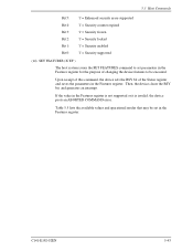
...of this command, the device sets the BSY bit of changing the device features to set in the Features register is not supported or it is invalid, the device posts an ABORTED COMMAND error. Then, the device clears the BSY bit, and generates an...interrupt. 5.3 Host Commands Bit 5: Bit 4: Bit 3: Bit 2: Bit 1: Bit 0: '1' = Enhanced security erase supported '1' = Security counter expired '1' = Security frozen '1' = Security locked '1' = Security enabled '1' = Security supported (14) SET FEATURES (X'EF') The host system issues the SET FEATURES command to be set parameters in the Features ...
...of this command, the device sets the BSY bit of changing the device features to set in the Features register is not supported or it is invalid, the device posts an ABORTED COMMAND error. Then, the device clears the BSY bit, and generates an...interrupt. 5.3 Host Commands Bit 5: Bit 4: Bit 3: Bit 2: Bit 1: Bit 0: '1' = Enhanced security erase supported '1' = Security counter expired '1' = Security frozen '1' = Security locked '1' = Security enabled '1' = Security supported (14) SET FEATURES (X'EF') The host system issues the SET FEATURES command to be set parameters in the Features ...

Manual/User Guide
Page 119
... X'03' to be selected. Upper 5 bits of the Sector Count register defines the transfer type and lower 3 bits specifies the binary mode value. The IDD supports following values in the Sector Count register value. If other value than below is specified, an ABORTED COMMAND error is posted. 5.3 Host Commands At command...
... X'03' to be selected. Upper 5 bits of the Sector Count register defines the transfer type and lower 3 bits specifies the binary mode value. The IDD supports following values in the Sector Count register value. If other value than below is specified, an ABORTED COMMAND error is posted. 5.3 Host Commands At command...

Manual/User Guide
Page 121
The IDD supports 2, 4, 8, 16 and 32 (sectors) as for these commands is then enabled. 5.3 Host Commands *3) Automatic Acoustic Management (AAM) The host writes to the Sector Count register ... the SET MULTIPLE MODE command. If the value of the Sector Count register is valid and is a supported block count, the value is enabled. If the contents of the Sector Count register is not a supported block count, an ABORTED COMMAND error is issued, the READ MULTIPLE and WRITE MULTIPLE commands are disabled...
The IDD supports 2, 4, 8, 16 and 32 (sectors) as for these commands is then enabled. 5.3 Host Commands *3) Automatic Acoustic Management (AAM) The host writes to the Sector Count register ... the SET MULTIPLE MODE command. If the value of the Sector Count register is valid and is a supported block count, the value is enabled. If the contents of the Sector Count register is not a supported block count, an ABORTED COMMAND error is issued, the READ MULTIPLE and WRITE MULTIPLE commands are disabled...

Manual/User Guide
Page 131
The READ LONG command supports only single sector operation. Number of ECC bytes to be transferred is fixed to 4 bytes and cannot be read) 1F7H(ST) 1F6H(DH) 1F5H(CH) ...
The READ LONG command supports only single sector operation. Number of ECC bytes to be transferred is fixed to 4 bytes and cannot be read) 1F7H(ST) 1F6H(DH) 1F5H(CH) ...

Manual/User Guide
Page 132
.... /LBA [MSB] Cylinder No. [MSB] / LBA Cylinder No. [LSB] / LBA Sector No. / LBA [LSB] xx Error information 5-58 C141-E192-02EN The WRITE LONG command supports only single sector operation. This command is operated under the following conditions: • READ LONG issued → WRITE LONG (Same address) issues sequence (After READ...
.... /LBA [MSB] Cylinder No. [MSB] / LBA Cylinder No. [LSB] / LBA Sector No. / LBA [LSB] xx Error information 5-58 C141-E192-02EN The WRITE LONG command supports only single sector operation. This command is operated under the following conditions: • READ LONG issued → WRITE LONG (Same address) issues sequence (After READ...