
Manual/User Guide
Page 16
... out burst 5-142 5.6.3.10 Host terminating an Ultra DMA data out burst 5-143 5.6.3.11 Device terminating an Ultra DMA data out burst 5-144 5.6.4 Power-on and reset 5-145 CHAPTER 6 Operations 6-1 6.1 Device Response to the Reset 6-2 6.1.1 Response to power-on 6-2 6.1.2 Response to hardware reset 6-3 6.1.3 Response to software reset 6-5 6.1.4 Response to diagnostic command 6-6 xii C141...
... out burst 5-142 5.6.3.10 Host terminating an Ultra DMA data out burst 5-143 5.6.3.11 Device terminating an Ultra DMA data out burst 5-144 5.6.4 Power-on and reset 5-145 CHAPTER 6 Operations 6-1 6.1 Device Response to the Reset 6-2 6.1.1 Response to power-on 6-2 6.1.2 Response to hardware reset 6-3 6.1.3 Response to software reset 6-5 6.1.4 Response to diagnostic command 6-6 xii C141...

Manual/User Guide
Page 19
... protocol 5-114 Figure 5.6 Protocol for the command execution without data transfer ...........5-115 Figure 5.7 Normal DMA data transfer 5-117 Figure 5.8 Ultra DMA termination with pull-up or pull-down 5-129 Figure 5.9 PIO data transfer timing 5-130 Figure 5.10 Multiword DMA data transfer ...Figure 5.20 Device terminating an Ultra DMA data out burst 5-144 Figure 5.21 Power-on Reset Timing 5-145 Figure 6.1 Figure 6.2 Figure 6.3 Figure 6.4 Figure 6.5 Figure 6.6 Figure 6.7 Response to power-on 6-3 Response to hardware reset 6-4 Response to software reset 6-5 Response to diagnostic command...
... protocol 5-114 Figure 5.6 Protocol for the command execution without data transfer ...........5-115 Figure 5.7 Normal DMA data transfer 5-117 Figure 5.8 Ultra DMA termination with pull-up or pull-down 5-129 Figure 5.9 PIO data transfer timing 5-130 Figure 5.10 Multiword DMA data transfer ...Figure 5.20 Device terminating an Ultra DMA data out burst 5-144 Figure 5.21 Power-on Reset Timing 5-145 Figure 6.1 Figure 6.2 Figure 6.3 Figure 6.4 Figure 6.5 Figure 6.6 Figure 6.7 Response to power-on 6-3 Response to hardware reset 6-4 Response to software reset 6-5 Response to diagnostic command...
Manual/User Guide
Page 88
... 3 Bit 2 Bit 1 Bit 0 HOB X X X X SRST nIEN 0 - Interface (2) Device Control register (X'3F6') The Device Control register contains device interrupt and software reset. The device can halt the uncompleted command execution only at execution of the EXT system command. When the BSY bit is 1 or the DRQ...Table 5.3 lists the supported commands, command code and the registers that selects higher-order information or lower-order information of hardware or software reset. handshake. - Bit 1: nIEN bit enables an interrupt (INTRQ signal) from the device to execute the DASP- When ...
... 3 Bit 2 Bit 1 Bit 0 HOB X X X X SRST nIEN 0 - Interface (2) Device Control register (X'3F6') The Device Control register contains device interrupt and software reset. The device can halt the uncompleted command execution only at execution of the EXT system command. When the BSY bit is 1 or the DRQ...Table 5.3 lists the supported commands, command code and the registers that selects higher-order information or lower-order information of hardware or software reset. handshake. - Bit 1: nIEN bit enables an interrupt (INTRQ signal) from the device to execute the DASP- When ...

Manual/User Guide
Page 118
...READ LONG and WRITE LONG commands. (*1) Disables the Acoustic management function. Enables the reverting to power-on default settings after software reset. (*1) *1 Although there is a response to Mode-0. Set the advanced power management mode to the command, nothing is... set as follows. Disables the reverting to power-on default settings after software reset. (*1) Disables the write cache function. Interface Table 5.5 Features register values and settable modes Features Register X'02' X'03' X'05...
...READ LONG and WRITE LONG commands. (*1) Disables the Acoustic management function. Enables the reverting to power-on default settings after software reset. (*1) *1 Although there is a response to Mode-0. Set the advanced power management mode to the command, nothing is... set as follows. Disables the reverting to power-on default settings after software reset. (*1) Disables the write cache function. Interface Table 5.5 Features register values and settable modes Features Register X'02' X'03' X'05...

Manual/User Guide
Page 121
... an interrupt. The IDD supports 2, 4, 8, 16 and 32 (sectors) as for "Performance mode", and low-speed seek by the drive across power on, hardware and software resets. If the value of sectors per block is written into the Sector Count register. Setting the seek mode by this command, the device sets...
... an interrupt. The IDD supports 2, 4, 8, 16 and 32 (sectors) as for "Performance mode", and low-speed seek by the drive across power on, hardware and software resets. If the value of sectors per block is written into the Sector Count register. Setting the seek mode by this command, the device sets...

Manual/User Guide
Page 139
...) X'99' or X'E6' x x x xx xx xx xx xx DV xx At command completion (I /O register outputs are in high-impedance state. All I /O registers contents to execute a software or hardware reset. The only way to release the device from sleep mode is to be read) 1F7H(ST) 1F6H(DH) 1F5H(CH) 1F4H(CL... generates an interrupt even if the device has not fully entered the sleep mode. In the sleep mode, the spindle motor is stopped and the ATA interface section is the only way to make the device enter the sleep mode. 5.3 Host Commands (27) SLEEP (X'99' or X'E6') This command is inactive...
...) X'99' or X'E6' x x x xx xx xx xx xx DV xx At command completion (I /O register outputs are in high-impedance state. All I /O registers contents to execute a software or hardware reset. The only way to release the device from sleep mode is to be read) 1F7H(ST) 1F6H(DH) 1F5H(CH) 1F4H(CL... generates an interrupt even if the device has not fully entered the sleep mode. In the sleep mode, the spindle motor is stopped and the ATA interface section is the only way to make the device enter the sleep mode. 5.3 Host Commands (27) SLEEP (X'99' or X'E6') This command is inactive...
Manual/User Guide
Page 166
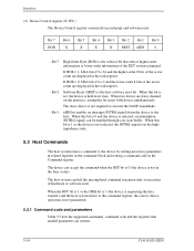
... SET, DEVICE CONFIGURATION FREEZE LOCK, DEVICE CONFIGURATION IDENTIFY, and DEVICE CONFIGURATION RESTORE commands are kept for the device power down , not cleared by a hardware or software reset. After execution of the Device Configuration Overlay settings. If the device has executed a previous DEVICE CONFIGURATION FREEZE LOCK command since power-up, an aborted...
... SET, DEVICE CONFIGURATION FREEZE LOCK, DEVICE CONFIGURATION IDENTIFY, and DEVICE CONFIGURATION RESTORE commands are kept for the device power down , not cleared by a hardware or software reset. After execution of the Device Configuration Overlay settings. If the device has executed a previous DEVICE CONFIGURATION FREEZE LOCK command since power-up, an aborted...
Manual/User Guide
Page 192
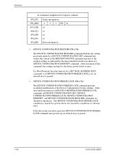
... the fastest mode of which the system operates. The Ultra DMA Mode selected by a host shall be less than or equal to other elements of the ATA protocol (e.g.: Command Block Register access). An Ultra DMA capable device shall retain its default nonUltra DMA Modes... after executing a Software reset sequence. All timing requirements for a selected Ultra DMA Mode shall be used for non-Ultra DMA transfers upon the negation of DMACK- Devices supporting Ultra DMA Mode 1 shall also support Ultra DMA Mode 0. Devices supporting Ultra DMA Mode 2 shall also support Ultra DMA Modes 0 and...
... the fastest mode of which the system operates. The Ultra DMA Mode selected by a host shall be less than or equal to other elements of the ATA protocol (e.g.: Command Block Register access). An Ultra DMA capable device shall retain its default nonUltra DMA Modes... after executing a Software reset sequence. All timing requirements for a selected Ultra DMA Mode shall be used for non-Ultra DMA transfers upon the negation of DMACK- Devices supporting Ultra DMA Mode 1 shall also support Ultra DMA Mode 0. Devices supporting Ultra DMA Mode 2 shall also support Ultra DMA Modes 0 and...

Manual/User Guide
Page 219
5.6 Timing 5.6.4 Power-on and reset Figure 5.21 shows power-on and reset (hardware and software reset) timing. (1) Only master device is present Clear Reset *1 Power-on RESETSoftware reset BSY tM tN DASPtP *1: Reset means including Power-on Reset...tP Time from RESET- Unit 25 - µs - 400 ns - 1 ms - 30 s - 400 ms - 31 s Figure 5.21 Power-on -Reset, Hardware Reset (RESET-), and Software Reset. (2) Master and slave devices are present (2-drives configuration) [Master device] BSY DASP- [Slave device] BSY PDIAG- negation to DASP- negation tQ Self-diagnostics execution...
5.6 Timing 5.6.4 Power-on and reset Figure 5.21 shows power-on and reset (hardware and software reset) timing. (1) Only master device is present Clear Reset *1 Power-on RESETSoftware reset BSY tM tN DASPtP *1: Reset means including Power-on Reset...tP Time from RESET- Unit 25 - µs - 400 ns - 1 ms - 30 s - 400 ms - 31 s Figure 5.21 Power-on -Reset, Hardware Reset (RESET-), and Software Reset. (2) Master and slave devices are present (2-drives configuration) [Master device] BSY DASP- [Slave device] BSY PDIAG- negation to DASP- negation tQ Self-diagnostics execution...

Manual/User Guide
Page 225
.... If a slave device is not received. signal. signal for up to see if the slave device has completed the self-diagnosis successfully. is checked for a software reset. X'3F6' Reg. Master device X"0C" or X"04" X"00" Status Reg. signal for up to 15 seconds to 31 seconds. When the IDD is...30 seconds after it is asserted if the command is present, the master device checks the PDIAG- 6.1 Device Response to the Reset 6.1.3 Response to software reset C141-E192-02EN 6-5 If the slave device is set to the master device as described below: PDIAG- Figure 6.3 Response to...
.... If a slave device is not received. signal. signal for up to see if the slave device has completed the self-diagnosis successfully. is checked for a software reset. X'3F6' Reg. Master device X"0C" or X"04" X"00" Status Reg. signal for up to 15 seconds to 31 seconds. When the IDD is...30 seconds after it is asserted if the command is present, the master device checks the PDIAG- 6.1 Device Response to the Reset 6.1.3 Response to software reset C141-E192-02EN 6-5 If the slave device is set to the master device as described below: PDIAG- Figure 6.3 Response to...

Manual/User Guide
Page 228
... disk medium cannot be made immediately. However if a command with disk access is minimal in the standby mode. • Reset (hardware or software) • STANDBY command • STANDBY IMMEDIATE command • INITIALIZE DEVICE PARAMETERS command • CHECK POWER MODE command (5) Sleep mode The ...power consumption of following condition: • A SLEEP command is to execute a software or hardware reset. When one of the drive is issued, response time to the command under the following commands is issued, the command ...
... disk medium cannot be made immediately. However if a command with disk access is minimal in the standby mode. • Reset (hardware or software) • STANDBY command • STANDBY IMMEDIATE command • INITIALIZE DEVICE PARAMETERS command • CHECK POWER MODE command (5) Sleep mode The ...power consumption of following condition: • A SLEEP command is to execute a software or hardware reset. When one of the drive is issued, response time to the command under the following commands is issued, the command ...

Manual/User Guide
Page 250
...145 resistor, pull-up or pull-down 5-129 response, to diagnostic command 6-6 hardware reset 6-3 power-on 6-2 software reset 6-5 response to diagnostic command 6-6 hardware reset 6-3 power-on 6-2 software reset 6-5 S sector slip processing 6-10 sequential command 6-16 sequential hit 6-16 sleep mode 6-8 spare area 6-9 ...standby mode 6-8 status report in event of error 6-20 sustain, Ultra DMA data in burst 5-136 out burst 5-141 sustained Ultra DMA data in burst...
...145 resistor, pull-up or pull-down 5-129 response, to diagnostic command 6-6 hardware reset 6-3 power-on 6-2 software reset 6-5 response to diagnostic command 6-6 hardware reset 6-3 power-on 6-2 software reset 6-5 S sector slip processing 6-10 sequential command 6-16 sequential hit 6-16 sleep mode 6-8 spare area 6-9 ...standby mode 6-8 status report in event of error 6-20 sustain, Ultra DMA data in burst 5-136 out burst 5-141 sustained Ultra DMA data in burst...