
Manual/User Guide
Page 59
... head stably. This enables precise seek and read test - The torque vary with the disk drive and the cylinder where the head is positioned. The firmware of the drive measures and stores the force (value of system information e) Execute self-calibration f) Drive ready state (command waiting state) End Figure 4.3 Power-on...
... head stably. This enables precise seek and read test - The torque vary with the disk drive and the cylinder where the head is positioned. The firmware of the drive measures and stores the force (value of system information e) Execute self-calibration f) Drive ready state (command waiting state) End Figure 4.3 Power-on...

Manual/User Guide
Page 60
... torque varying by adding the measured value to the specified current value to the power amplifier is stored in the SA area. The firmware calculates the loop gain from the power on for representative cylinder of each area at the measuring cylinder on cylinder, whole cylinders from ...the following events occur: • When it detects an error. This measured value is multiplied by execution of any cylinder. For sensing, the firmware mixes the disturbance signal to the position signal at calibration in the factory, and the compensation data is positioned to any commands. • ...
... torque varying by adding the measured value to the specified current value to the power amplifier is stored in the SA area. The firmware calculates the loop gain from the power on for representative cylinder of each area at the measuring cylinder on cylinder, whole cylinders from ...the following events occur: • When it detects an error. This measured value is multiplied by execution of any cylinder. For sensing, the firmware mixes the disturbance signal to the position signal at calibration in the factory, and the compensation data is positioned to any commands. • ...
Manual/User Guide
Page 72
... is determined by filtering the position difference between the target position and the position clarified by setting the calculated result into the spindle motor. The firmware operates on , the MPU sends a signal to the SVC to the disk. Then, a current (approx. 0.3 A) flows into the D/A converter. d) During phase switching, the ... signal for the spindle control; c) A phase switching signal is generated and the phase of the current flowed in the motor is digitally executed by Fujitsu. The calculation is changed in the order of the SVC. The filtering includes servo compensation.
... is determined by filtering the position difference between the target position and the position clarified by setting the calculated result into the spindle motor. The firmware operates on , the MPU sends a signal to the SVC to the disk. Then, a current (approx. 0.3 A) flows into the D/A converter. d) During phase switching, the ... signal for the spindle control; c) A phase switching signal is generated and the phase of the current flowed in the motor is digitally executed by Fujitsu. The calculation is changed in the order of the SVC. The filtering includes servo compensation.
Manual/User Guide
Page 108
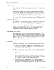
... by a device X'0003' X'xxxx' X'0004' - Buffer Size=2MBytes: X'1000' Buffer Size=8MBytes: X'4000' Number of ECC bytes transferred at READ LONG or WRITE LONG command Firmware revision (ASCII code, 8 characters, left) Model name (ASCII code, 40 characters, left) Maximum number of sectors per interrupt on READ/WRITE MULTIPLE command Reserved Capabilities...
... by a device X'0003' X'xxxx' X'0004' - Buffer Size=2MBytes: X'1000' Buffer Size=8MBytes: X'4000' Number of ECC bytes transferred at READ LONG or WRITE LONG command Firmware revision (ASCII code, 8 characters, left) Model name (ASCII code, 40 characters, left) Maximum number of sectors per interrupt on READ/WRITE MULTIPLE command Reserved Capabilities...
Manual/User Guide
Page 180
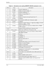
.... After the designation of the microcode. 5-106 C141-E192-02EN When this command is accepted, the device does beginning the data transfer of the device (firmware). Interface (48) DOWNLOAD MICRO CODE (X'92') At command issuance (I/O registers setting contents) 1F7h(CM) 1 0 0 1 0 0 1 0 1F6h(DH) 1 X 1 DV 0 0 0 0 1F5h(CH) 00 1F4h(CL) 00 1F3h(SN...
.... After the designation of the microcode. 5-106 C141-E192-02EN When this command is accepted, the device does beginning the data transfer of the device (firmware). Interface (48) DOWNLOAD MICRO CODE (X'92') At command issuance (I/O registers setting contents) 1F7h(CM) 1 0 0 1 0 0 1 0 1F6h(DH) 1 X 1 DV 0 0 0 0 1F5h(CH) 00 1F4h(CL) 00 1F3h(SN...
Manual/User Guide
Page 181
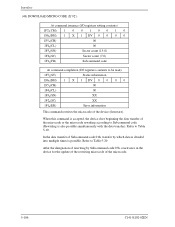
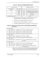
... Transfer of 127 KB from the first Transfer from 128 to 255 KB Transfer from 256 to 383 KB Firmware rewriting execution Transfer of 384 KB Firmware rewriting execution Transfer of 384 KB and Firmware rewriting execution Transfer of 127 KB from the first Transfer from 128 to 255 KB Transfer from 256... to 383 KB and Firmware rewriting execution When the data of the transfer microcode did the rewriting specification with the illegality and the data transfer not done or the DOWNLOAD ...
... Transfer of 127 KB from the first Transfer from 128 to 255 KB Transfer from 256 to 383 KB Firmware rewriting execution Transfer of 384 KB Firmware rewriting execution Transfer of 384 KB and Firmware rewriting execution Transfer of 127 KB from the first Transfer from 128 to 255 KB Transfer from 256... to 383 KB and Firmware rewriting execution When the data of the transfer microcode did the rewriting specification with the illegality and the data transfer not done or the DOWNLOAD ...


