Manual/User Guide
Page 1
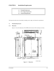
CHAPTER 4 Installation Requirements 4.1 Mounting Requirements 4.2 Power Supply Requirements 4.3 Connection Requirements This chapter describes the environmental, mounting, power supply, and connection requirements. 4.1 Mounting Requirements 4.1.1 Dimensions Figures 4.1 show the dimensions of the HDD and the location of the mounting screw holes. C141-E219 Figure 4.1 Dimensions [Units: mm] 4-1
CHAPTER 4 Installation Requirements 4.1 Mounting Requirements 4.2 Power Supply Requirements 4.3 Connection Requirements This chapter describes the environmental, mounting, power supply, and connection requirements. 4.1 Mounting Requirements 4.1.1 Dimensions Figures 4.1 show the dimensions of the HDD and the location of the mounting screw holes. C141-E219 Figure 4.1 Dimensions [Units: mm] 4-1

Manual/User Guide
Page 2
Installation Requirements 4.1.2 Mounting orientations The permissible orientations of the HDD are shown in Figure 4.2, the drive can be installed flat on any of the angle is ±5° from a vertical or horizontal plane should not exceed 5°. (a) Horizontal -1 (b) Horizontal -2 (c) Vertical -1 (d) Vertical -2 (e) Upright mounting -1 (f) Upright mounting -2 Direction of gravity Figure 4.2 HDD orientations 4-2 C141-E219 As show in Figure 4.2, and the tolerance of its six sides. Inclination from the horizontal plane.
Installation Requirements 4.1.2 Mounting orientations The permissible orientations of the HDD are shown in Figure 4.2, the drive can be installed flat on any of the angle is ±5° from a vertical or horizontal plane should not exceed 5°. (a) Horizontal -1 (b) Horizontal -2 (c) Vertical -1 (d) Vertical -2 (e) Upright mounting -1 (f) Upright mounting -2 Direction of gravity Figure 4.2 HDD orientations 4-2 C141-E219 As show in Figure 4.2, and the tolerance of its six sides. Inclination from the horizontal plane.

Manual/User Guide
Page 3
... 4.1 Mounting Requirements Damage Never remove any way. (1) The mounting screws must use the frame with 0.49N·m (5kgf·cm) ±12%. Mount the HDD with making a gap of 2.5 mm or more between the HDD and the frame of mounting ...Use all 4 mounting holds on the both sides. (4) Limitation of the screw from the drive or deface them in Figure 4.3, use M3 × 0.5 metric (2) Examples of the system. c) Tightening torque of screw must be secured with an embossed structure, or the like. d) Impact caused by the electric screwdriver must be within the drive specifications...
... 4.1 Mounting Requirements Damage Never remove any way. (1) The mounting screws must use the frame with 0.49N·m (5kgf·cm) ±12%. Mount the HDD with making a gap of 2.5 mm or more between the HDD and the frame of mounting ...Use all 4 mounting holds on the both sides. (4) Limitation of the screw from the drive or deface them in Figure 4.3, use M3 × 0.5 metric (2) Examples of the system. c) Tightening torque of screw must be secured with an embossed structure, or the like. d) Impact caused by the electric screwdriver must be within the drive specifications...

Manual/User Guide
Page 4
Installation Requirements Figure 4.3 Mounting frame structure (5) Never cover the vent hole as shown in Figure 4.4. Vent hole Label Figure 4.4 Breathing hole location 4-4 C141-E219
Installation Requirements Figure 4.3 Mounting frame structure (5) Never cover the vent hole as shown in Figure 4.4. Vent hole Label Figure 4.4 Breathing hole location 4-4 C141-E219
Manual/User Guide
Page 5
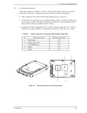
... especially with ambient temperature measured 30 mm from the disk drive. These measurement results must satisfy the temperature condition listed in a cabinet is a condition for assuring an MTBF of 1,400,000 hours, requires an air flow of specific ICs and the DE. Measurement point 1 DE Surface 2 Read channel LSI 3 VCM/SPM Driver 4 HDC 5 MPU Maximum temperature 60°C 80...
... especially with ambient temperature measured 30 mm from the disk drive. These measurement results must satisfy the temperature condition listed in a cabinet is a condition for assuring an MTBF of 1,400,000 hours, requires an air flow of specific ICs and the DE. Measurement point 1 DE Surface 2 Read channel LSI 3 VCM/SPM Driver 4 HDC 5 MPU Maximum temperature 60°C 80...

Manual/User Guide
Page 6
... Y] • Interface connection [Surface Z] • Holes for mounting screw [Surface X] • Holes for mounting screw (Both Side) Figure 4.6 Service clearance area (8) Environmental magnetic field Do not install the HDD in the vicinity of equipment giving off strong magnetic fields, such as monitors, televisions, or loudspeakers. (9) Leakage magnetic flux Do not mount the HDD near the devices that...
... Y] • Interface connection [Surface Z] • Holes for mounting screw [Surface X] • Holes for mounting screw (Both Side) Figure 4.6 Service clearance area (8) Environmental magnetic field Do not install the HDD in the vicinity of equipment giving off strong magnetic fields, such as monitors, televisions, or loudspeakers. (9) Leakage magnetic flux Do not mount the HDD near the devices that...

Manual/User Guide
Page 7
a) Control the sending of the NOTIFY (ENABLE SPINUP) primitive so that the spindle motors of individual disk drives are started sequentially using one HDD is turned on to start the spindle motors sequentially. C141-E219 4-7 b) Turn on /off sequence of +5V DC and +12V DC, supplied to the HDD, does not matter. (4) Sequential starting of spindle motors After power is...
a) Control the sending of the NOTIFY (ENABLE SPINUP) primitive so that the spindle motors of individual disk drives are started sequentially using one HDD is turned on to start the spindle motors sequentially. C141-E219 4-7 b) Turn on /off sequence of +5V DC and +12V DC, supplied to the HDD, does not matter. (4) Sequential starting of spindle motors After power is...

Manual/User Guide
Page 8
The specification of interface connector. Interface connector (CN1) (power lines included) Figure 4.9 Connector location 4-8 C141-E219 Figure 4.8 AC noise filter (recommended) 4.3 Connection Requirements 4.3.1 Connector Figure 4.9 shows the locations of this noise filter is recommended. Installation Requirements (5) Noise filter To eliminate AC line noise, a noise filter should be installed at 10 MHz • Circuit construction: T-configuration as shown in Figure 4.8 is as follows: • Attenuation: 40 dB or more at the AC input terminal on the HDD power supply unit.
The specification of interface connector. Interface connector (CN1) (power lines included) Figure 4.9 Connector location 4-8 C141-E219 Figure 4.8 AC noise filter (recommended) 4.3 Connection Requirements 4.3.1 Connector Figure 4.9 shows the locations of this noise filter is recommended. Installation Requirements (5) Noise filter To eliminate AC line noise, a noise filter should be installed at 10 MHz • Circuit construction: T-configuration as shown in Figure 4.8 is as follows: • Attenuation: 40 dB or more at the AC input terminal on the HDD power supply unit.
Manual/User Guide
Page 9
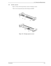
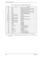
4.3 Connection Requirements 4.3.2 Interface connector Figure 4.10 shows the SAS type interface connector (SAS plug) overview. S1 S7 P1 P15 S14 S8 Figure 4.10 SAS plug connector overview C141-E219 4-9 Table 4.2 lists the signal allocation of the SAS plug on the HDD.
4.3 Connection Requirements 4.3.2 Interface connector Figure 4.10 shows the SAS type interface connector (SAS plug) overview. S1 S7 P1 P15 S14 S8 Figure 4.10 SAS plug connector overview C141-E219 4-9 Table 4.2 lists the signal allocation of the SAS plug on the HDD.
Manual/User Guide
Page 10
... used Not used Not used on MAV2073RC and MAV2036RC. 4-10 C141-E219 Note 2) P1 to P3 are SAS Secondary Port signals, and not used GROUND GROUND GROUND Pre-charge pin for +5V +5V power supply input +5V power supply input GROUND READY LED output GROUND Pre-charge pin for +12V +12V power supply input +12V power supply input Note 1) S8 - Installation Requirements Table 4.2 Interface connector (SAS plug) signal allocation:CN1 Pin...
... used Not used Not used on MAV2073RC and MAV2036RC. 4-10 C141-E219 Note 2) P1 to P3 are SAS Secondary Port signals, and not used GROUND GROUND GROUND Pre-charge pin for +5V +5V power supply input +5V power supply input GROUND READY LED output GROUND Pre-charge pin for +12V +12V power supply input +12V power supply input Note 1) S8 - Installation Requirements Table 4.2 Interface connector (SAS plug) signal allocation:CN1 Pin...


