Manual/User Guide
Page 4
Document number T10/1236D Rev.20 [NCITS.351:2001] T10/996D Rev.8c [NCITS.306:1998] T10/1157D Rev.20 T10/1365D Rev.7 Title SCSI Primary Commands-2 (SPC-2) SCSI-3 Block Commands (SBC) SCSI Architecture Model-2 (SAM-2) SCSI Parallel Interface-4 (SPI-4) *1 ANSI = American National Standard Institute In case of conflict between this manual and any referenced document, this manual comply with the following ANSI (*1) standards. ii C141-E185 Related Standards Product specifications and functions described in this manual takes precedence.
Document number T10/1236D Rev.20 [NCITS.351:2001] T10/996D Rev.8c [NCITS.306:1998] T10/1157D Rev.20 T10/1365D Rev.7 Title SCSI Primary Commands-2 (SPC-2) SCSI-3 Block Commands (SBC) SCSI Architecture Model-2 (SAM-2) SCSI Parallel Interface-4 (SPI-4) *1 ANSI = American National Standard Institute In case of conflict between this manual and any referenced document, this manual comply with the following ANSI (*1) standards. ii C141-E185 Related Standards Product specifications and functions described in this manual takes precedence.
Manual/User Guide
Page 7
...-data is divided into 4 interleaving sectors, and ECC is off the power. Hot temperature To prevent injury, do not handle the drive until after the device has 5-1 cooled sufficiently after turning off the power. Do not change the setting of read sector keeps allowable error... byte number, correction is on . • Write protect: CN2 9-10 (NP model only) 3. Do not change the setting of terminals except following setting pins during operation and remain hot immediately after turning off before connecting or disconnecting...
...-data is divided into 4 interleaving sectors, and ECC is off the power. Hot temperature To prevent injury, do not handle the drive until after the device has 5-1 cooled sufficiently after turning off the power. Do not change the setting of read sector keeps allowable error... byte number, correction is on . • Write protect: CN2 9-10 (NP model only) 3. Do not change the setting of terminals except following setting pins during operation and remain hot immediately after turning off before connecting or disconnecting...

Manual/User Guide
Page 11
... page CHAPTER 1 GENERAL DESCRIPTION 1-1 1.1 Standard Features ...1-2 1.2 Hardware Structure...1-6 1.3 System Configuration ...1-9 CHAPTER 2 SPECIFICATIONS 2-1 2.1 Hardware Specifications...2-1 2.1.1 Model name and order number 2-1 2.1.2 Function specifications...2-2 2.1.3 Environmental specifications 2-4 2.1.4 Error rate ...2-5 2.1.5 Reliability...2-5 2.2 SCSI Function Specifications 2-7 CHAPTER 3 ...Mounting ...4-4 4.1.3 Notes on mounting ...4-4 4.2 Power Supply Requirements 4-8 4.3 Connection Requirements 4-11 4.3.1 SCA2 connector type 16-bit SCSI model (NC model 4-11 C141-E185 ix
... page CHAPTER 1 GENERAL DESCRIPTION 1-1 1.1 Standard Features ...1-2 1.2 Hardware Structure...1-6 1.3 System Configuration ...1-9 CHAPTER 2 SPECIFICATIONS 2-1 2.1 Hardware Specifications...2-1 2.1.1 Model name and order number 2-1 2.1.2 Function specifications...2-2 2.1.3 Environmental specifications 2-4 2.1.4 Error rate ...2-5 2.1.5 Reliability...2-5 2.2 SCSI Function Specifications 2-7 CHAPTER 3 ...Mounting ...4-4 4.1.3 Notes on mounting ...4-4 4.2 Power Supply Requirements 4-8 4.3 Connection Requirements 4-11 4.3.1 SCA2 connector type 16-bit SCSI model (NC model 4-11 C141-E185 ix
Manual/User Guide
Page 12
...model (NP model 4-13 Cable connector requirements 4-20 External operator panel (on NP model drives only 4-21 CHAPTER 5 INSTALLATION 5-1 5.1 Notes on Handling Drives 5-1 5.2 Connections...5-3 5.3 Setting Terminals ...5-5 5.3.1 SCSI ID setting...5-6 5.3.2 Each mode setting ...5-8 5.3.3 Mode settings ...5-10 5.4 Mounting Drives...5-13 5.6.2 Checking SCSI connection 5-14 5.6.3 Formatting ...5-17 5.6.4 Setting parameters ...5-19 5.7 Dismounting Drives...5-23 5.8 Spare Disk Drive ...5-23 CHAPTER 6 DIAGNOSTICS AND MAINTENANCE 6-1 6.1 Diagnostics ...6-1 6.1.1 Self-diagnostics ...6-1 6.1.2 Test ...
...model (NP model 4-13 Cable connector requirements 4-20 External operator panel (on NP model drives only 4-21 CHAPTER 5 INSTALLATION 5-1 5.1 Notes on Handling Drives 5-1 5.2 Connections...5-3 5.3 Setting Terminals ...5-5 5.3.1 SCSI ID setting...5-6 5.3.2 Each mode setting ...5-8 5.3.3 Mode settings ...5-10 5.4 Mounting Drives...5-13 5.6.2 Checking SCSI connection 5-14 5.6.3 Formatting ...5-17 5.6.4 Setting parameters ...5-19 5.7 Dismounting Drives...5-23 5.8 Spare Disk Drive ...5-23 CHAPTER 6 DIAGNOSTICS AND MAINTENANCE 6-1 6.1 Diagnostics ...6-1 6.1.1 Self-diagnostics ...6-1 6.1.2 Test ...
Manual/User Guide
Page 13
...6.4.2 6.4.3 6.4.4 6.4.5 Diagnostic test ...6-12 Troubleshooting Procedures 6-13 Outline of troubleshooting procedures 6-13 Troubleshooting with disk drive replacement in the field 6-13 Troubleshooting at the repair site 6-15 Troubleshooting with parts replacement in the factory ...), (B-47-xx), (B-49-00), (B-4D-xx) and (B-4E-00): SCSI interface error 7-4 APPENDIX A SETTING TERMINALS A-1 A.1 Setting Terminals (on NP model only A-2 APPENDIX B CONNECTOR SIGNAL ALLOCATION B-1 B.1 SCSI Connector Signal Allocation: SCA2 type LVD 16-bit SCSI B-2 B.2 SCSI Connector Signal Allocation: 68 pin ...
...6.4.2 6.4.3 6.4.4 6.4.5 Diagnostic test ...6-12 Troubleshooting Procedures 6-13 Outline of troubleshooting procedures 6-13 Troubleshooting with disk drive replacement in the field 6-13 Troubleshooting at the repair site 6-15 Troubleshooting with parts replacement in the factory ...), (B-47-xx), (B-49-00), (B-4D-xx) and (B-4E-00): SCSI interface error 7-4 APPENDIX A SETTING TERMINALS A-1 A.1 Setting Terminals (on NP model only A-2 APPENDIX B CONNECTOR SIGNAL ALLOCATION B-1 B.1 SCSI Connector Signal Allocation: SCA2 type LVD 16-bit SCSI B-2 B.2 SCSI Connector Signal Allocation: 68 pin ...
Manual/User Guide
Page 14
FIGURES Figure 1.1 Figure 1.2 Figure 1.3 Figure 1.4 page NC model drives outer view 1-6 NP model drives outer view 1-6 Disk/head configuration...1-7 System configuration ...1-9 Figure 3.1 Figure 3.2 Figure 3.3 Figure 3.4 Figure 3.5 Figure 3.6 Figure 3.7 Figure 3.8 Cylinder configuration...3-2 Spare area in cell ...3-5 Alternate cylinder ...3-5 Track format ...3-6 ...
FIGURES Figure 1.1 Figure 1.2 Figure 1.3 Figure 1.4 page NC model drives outer view 1-6 NP model drives outer view 1-6 Disk/head configuration...1-7 System configuration ...1-9 Figure 3.1 Figure 3.2 Figure 3.3 Figure 3.4 Figure 3.5 Figure 3.6 Figure 3.7 Figure 3.8 Cylinder configuration...3-2 Spare area in cell ...3-5 Alternate cylinder ...3-5 Track format ...3-6 ...

Manual/User Guide
Page 15
... cables connection ...4-19 External operator panel circuit example 4-21 Figure 5.1 Figure 5.2 Figure 5.3 Figure 5.4 Figure 5.5 SCSI bus connections ...5-4 Setting terminals location (on NP models only 5-5 CN2 setting terminal (on NP models only 5-6 Checking the SCSI connection (A 5-15 Checking the SCSI connection (B 5-16 Figure 6.1 Figure 6.2 Figure 6.3 Revision label ...6-9 Indicating revision numbers 6-10 Test flowchart...
... cables connection ...4-19 External operator panel circuit example 4-21 Figure 5.1 Figure 5.2 Figure 5.3 Figure 5.4 Figure 5.5 SCSI bus connections ...5-4 Setting terminals location (on NP models only 5-5 CN2 setting terminal (on NP models only 5-6 Checking the SCSI connection (A 5-15 Checking the SCSI connection (B 5-16 Figure 6.1 Figure 6.2 Figure 6.3 Revision label ...6-9 Indicating revision numbers 6-10 Test flowchart...
Manual/User Guide
Page 16
... mode settings (by CHANGE DEFINITION command 5-10 Table 5.8 Setting check list (NP model only 5-11 Table 6.1 Self-diagnostic functions ...6-1 Table 6.2 System-level field troubleshooting 6-14 Table 6.3 Disk drive troubleshooting ...6-15 Table 7.1 Definition of sense data ...7-3 Table A.1 CN2 setting terminal (on NP model drives only A-2 Table B.1 SCSI connector (SCA2 type LVD 16-bit SCSI): CN1...
... mode settings (by CHANGE DEFINITION command 5-10 Table 5.8 Setting check list (NP model only 5-11 Table 6.1 Self-diagnostic functions ...6-1 Table 6.2 System-level field troubleshooting 6-14 Table 6.3 Disk drive troubleshooting ...6-15 Table 7.1 Definition of sense data ...7-3 Table A.1 CN2 setting terminal (on NP model drives only A-2 Table B.1 SCSI connector (SCA2 type LVD 16-bit SCSI): CN1...

Manual/User Guide
Page 18
... data bus is available only with the large capacity buffer in the standard 3.5 type fixed disk drive form factor, the IDD is 320 MB/s maximum at the paced transfer synchronous mode. 1-2 C141...16-bit SCSI: The data transfer rate on the SCSI bus is extremely compact. For the ultra SCSI model, number of the bus width setting. This allows software to the SCSI bus of the host system. ... bus width (16-bit SCSI), which have the wide transfer function suitable for NP model) • 16-bit SCSI: 16 drives max. (4) High speed data transfer Such a high data transfer rate on the SCSI bus...
... data bus is available only with the large capacity buffer in the standard 3.5 type fixed disk drive form factor, the IDD is 320 MB/s maximum at the paced transfer synchronous mode. 1-2 C141...16-bit SCSI: The data transfer rate on the SCSI bus is extremely compact. For the ultra SCSI model, number of the bus width setting. This allows software to the SCSI bus of the host system. ... bus width (16-bit SCSI), which have the wide transfer function suitable for NP model) • 16-bit SCSI: 16 drives max. (4) High speed data transfer Such a high data transfer rate on the SCSI bus...

Manual/User Guide
Page 22
1.2 Hardware Structure An outer view of the IDD is composed of the disk, head, spindle motor, mounted disk enclosure (DE) with actuator and air circulation filter, as well as read/write pre-amp with the printed circuit assembly (PCA) of the controller. Figure 1.1 NC model drives outer view Figure 1.2 NP model drives outer view 1-6 C141-E185 The IDD is given in Figures 1.1 and 1.2.
1.2 Hardware Structure An outer view of the IDD is composed of the disk, head, spindle motor, mounted disk enclosure (DE) with actuator and air circulation filter, as well as read/write pre-amp with the printed circuit assembly (PCA) of the controller. Figure 1.1 NC model drives outer view Figure 1.2 NP model drives outer view 1-6 C141-E185 The IDD is given in Figures 1.1 and 1.2.

Manual/User Guide
Page 23
Each model contains following number of disks and heads Base Cover MAS3735NC/NP 0 1 2 3 4 5 6 7 MAS3367NC/NP 0 1 2 3 MAS3184NC/NP 0 1 Figure 1.3 Disk/head configuration (3) Spindle motor The disks are not rotating, and automatically float when the rotation is stopped. The ... diameter of 25 mm (0.98 inch) for at the end of the actuator arm is controlled by a direct-drive hall-less DC motor. The heads at least 20,000 contact starts and stops. MAS3735NC/NP: 4 MAS3367NC/NP: 2 MAS3184NC/NP: 1 (2) Heads The MR (Magnet - Resistive) of the CSS (contact start/stop) type heads...
Each model contains following number of disks and heads Base Cover MAS3735NC/NP 0 1 2 3 4 5 6 7 MAS3367NC/NP 0 1 2 3 MAS3184NC/NP 0 1 Figure 1.3 Disk/head configuration (3) Spindle motor The disks are not rotating, and automatically float when the rotation is stopped. The ... diameter of 25 mm (0.98 inch) for at the end of the actuator arm is controlled by a direct-drive hall-less DC motor. The heads at least 20,000 contact starts and stops. MAS3735NC/NP: 4 MAS3367NC/NP: 2 MAS3184NC/NP: 1 (2) Heads The MR (Magnet - Resistive) of the CSS (contact start/stop) type heads...

Manual/User Guide
Page 26
For input/output operation, a peripheral device attached to the SCSI bus that the whole volume of disk drive is addressed in unit called as logical unit. The IDD is constructed so that operates as target is a single logical unit, the selectable number of ... multi-SCSI devices. (2) Addressing of SCSI ID and LUN are as follows: • SCSI ID: • LUN: 8-bit SCSI:Selectable from 0 to 7 (option for NP model, switch selectable) 16-bit SCSI:Selectable from 0 to 15 (switch selectable) 0 (fixed) 1-10 C141-E185
For input/output operation, a peripheral device attached to the SCSI bus that the whole volume of disk drive is addressed in unit called as logical unit. The IDD is constructed so that operates as target is a single logical unit, the selectable number of ... multi-SCSI devices. (2) Addressing of SCSI ID and LUN are as follows: • SCSI ID: • LUN: 8-bit SCSI:Selectable from 0 to 7 (option for NP model, switch selectable) 16-bit SCSI:Selectable from 0 to 15 (switch selectable) 0 (fixed) 1-10 C141-E185
Manual/User Guide
Page 27
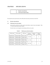
...order number. The data format can be changed by reinitializing with the user's system. Table 2.1 Model names and order numbers Model name MAS3735NC MAS3735NP MAS3367NC MAS3367NP MAS3184NC MAS3184NP Order number CA06227-B400 CA06227-B460 CA06227-B200 CA06227-B260 CA06227-B100 ...area) disks 73.49 GB 4 36.77 GB 2 18.37 GB 1 Number of the SCSI. 2.1 Hardware Specifications 2.1.1 Model name and order number Each model has a different recording capacities and interface connector type when shipped. CHAPTER 2 SPECIFICATIONS 2.1 Hardware Specifications 2.2 SCSI Function Specifications This ...
...order number. The data format can be changed by reinitializing with the user's system. Table 2.1 Model names and order numbers Model name MAS3735NC MAS3735NP MAS3367NC MAS3367NP MAS3184NC MAS3184NP Order number CA06227-B400 CA06227-B460 CA06227-B200 CA06227-B260 CA06227-B100 ...area) disks 73.49 GB 4 36.77 GB 2 18.37 GB 1 Number of the SCSI. 2.1 Hardware Specifications 2.1.1 Model name and order number Each model has a different recording capacities and interface connector type when shipped. CHAPTER 2 SPECIFICATIONS 2.1 Hardware Specifications 2.2 SCSI Function Specifications This ...

Manual/User Guide
Page 33
... resistor is mounted on the PCA × TERMPWR signal send function Ο Connector 68 pin P cable connector 80 pin SCA2 connector Ο (NP model) Ο (NC model) Data bus parity (Data bus CRC) Ο Bus arbitration function Ο Disconnection/reconnection function Ο Addressing SCSI ID 16-bit SCSI LUN (logical unit...
... resistor is mounted on the PCA × TERMPWR signal send function Ο Connector 68 pin P cable connector 80 pin SCA2 connector Ο (NP model) Ο (NC model) Data bus parity (Data bus CRC) Ο Bus arbitration function Ο Disconnection/reconnection function Ο Addressing SCSI ID 16-bit SCSI LUN (logical unit...
Manual/User Guide
Page 43
Table 3.4 Format capacity Model Data heads Data block length MAS3735NC/NP 8 MAS3367NC/NP 4 512 MAS3184NC/NP 2 User blocks ... be used . The INIT specifies the data to calculate the format capacity. [Number of sectors of each drive. C141-E185 3-9 Table 3.4 lists examples of alternate spare sectors per cell - The following is a function... sectors in the alternate cylinders. 3.2 Logical Data Block Addressing Independently of the physical structure of the disk drive, the IDD adopts the logical data block addressing as a data access method on the IDD (format capacity...
Table 3.4 Format capacity Model Data heads Data block length MAS3735NC/NP 8 MAS3367NC/NP 4 512 MAS3184NC/NP 2 User blocks ... be used . The INIT specifies the data to calculate the format capacity. [Number of sectors of each drive. C141-E185 3-9 Table 3.4 lists examples of alternate spare sectors per cell - The following is a function... sectors in the alternate cylinders. 3.2 Logical Data Block Addressing Independently of the physical structure of the disk drive, the IDD adopts the logical data block addressing as a data access method on the IDD (format capacity...
Manual/User Guide
Page 57
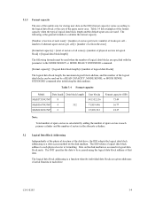
Therefore, a leak magnetic flux at surface of the IDD is shown in Figure 4.7. [Surface P'] • Setting terminal (MP model only) • External operator panel connector [Surface P] • Cable connection [Surface R] • Hole for mounting screw [Surface Q] • Hole for installation... area, or the sides which must allow access to the IDD for mounting screw Figure 4.7 Service clearance area (6) External magnetic field The drive should not be installed near the ferromagnetic body like a speaker to avoid the influence of the external magnetic field. (7) Leak magnetic flux ...
Therefore, a leak magnetic flux at surface of the IDD is shown in Figure 4.7. [Surface P'] • Setting terminal (MP model only) • External operator panel connector [Surface P] • Cable connection [Surface R] • Hole for mounting screw [Surface Q] • Hole for installation... area, or the sides which must allow access to the IDD for mounting screw Figure 4.7 Service clearance area (6) External magnetic field The drive should not be installed near the ferromagnetic body like a speaker to avoid the influence of the external magnetic field. (7) Leak magnetic flux ...

Manual/User Guide
Page 60
... spindle motors should be started by setting CN1-38 pin to open and CN1-78 pin to short. For the NC model drives, the spindle motors should be started after a delay of 12 seconds times [SCSI ID] by the following procedures. A method of power supply to the terminating ... start control mode, see Subsection 5.3.2. SCSI ID 0 1 2... 15 Delay time of spindle motor starting of spindle motors After power is turned on the IDD (NP model only).
... spindle motors should be started by setting CN1-38 pin to open and CN1-78 pin to short. For the NC model drives, the spindle motors should be started after a delay of 12 seconds times [SCSI ID] by the following procedures. A method of power supply to the terminating ... start control mode, see Subsection 5.3.2. SCSI ID 0 1 2... 15 Delay time of spindle motor starting of spindle motors After power is turned on the IDD (NP model only).

Manual/User Guide
Page 61
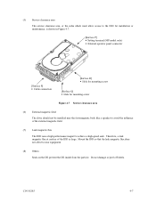
Figure 4.12 AC noise filter (recommended) 4.3 Connection Requirements 4.3.1 SCA2 connector type 16-bit SCSI model (NC model) (1) Connectors Figure 4.13 shows the locations of connectors on the SCA2 connector type 16-bit SCSI model (NC model). SCSI connector (CN1) (including power supply) Figure 4.13 NC connectors location C141-E185 4-11
Figure 4.12 AC noise filter (recommended) 4.3 Connection Requirements 4.3.1 SCA2 connector type 16-bit SCSI model (NC model) (1) Connectors Figure 4.13 shows the locations of connectors on the SCA2 connector type 16-bit SCSI model (NC model). SCSI connector (CN1) (including power supply) Figure 4.13 NC connectors location C141-E185 4-11

Manual/User Guide
Page 62
... This connector is not available for the SCSI bus is included in the SCSI connector. (2) SCSI connector and power supply connector The connector for NC model drives. 4-12 C141-E185 See Section B.1 in SCSI Physical Interface Specifications. The power connector is an unshielded SCA-2 connector conforming to Sections 1.3 and 1.4 in Appendix B for...
... This connector is not available for the SCSI bus is included in the SCSI connector. (2) SCSI connector and power supply connector The connector for NC model drives. 4-12 C141-E185 See Section B.1 in SCSI Physical Interface Specifications. The power connector is an unshielded SCA-2 connector conforming to Sections 1.3 and 1.4 in Appendix B for...

Manual/User Guide
Page 63
See Section B.2 in Appendix B for the signal assignments on the 68 pin connector type 16-bit SCSI model (NP model). • Power supply connector • SCSI connector • External operator panel connector External operator panel connector (CN2) Power supply connector (CN1) ... bus is an unshielded P connector conforming to Sections 1.3 and 1.4 in the SCSI Physical Interface Specifications. 4.3.2 68 pin connector type 16-bit SCSI model (NP model) (1) Connectors Figures 4.15 show the locations of the interface signals, refer to SCSI-3 type which has two 34-pin rows spaced 1.27 mm ...
See Section B.2 in Appendix B for the signal assignments on the 68 pin connector type 16-bit SCSI model (NP model). • Power supply connector • SCSI connector • External operator panel connector External operator panel connector (CN2) Power supply connector (CN1) ... bus is an unshielded P connector conforming to Sections 1.3 and 1.4 in the SCSI Physical Interface Specifications. 4.3.2 68 pin connector type 16-bit SCSI model (NP model) (1) Connectors Figures 4.15 show the locations of the interface signals, refer to SCSI-3 type which has two 34-pin rows spaced 1.27 mm ...

