Manual/User Guide
Page 4
Related Standards Product specifications and functions described in this manual takes precedence. Document number T10/1236D Rev.20 [NCITS.351:2001] T10/996D Rev.8c [NCITS.306:1998] T10/1157D Rev.20 T10/1365D Rev.7 Title SCSI Primary Commands-2 (SPC-2) SCSI-3 Block Commands (SBC) SCSI Architecture Model-2 (SAM-2) SCSI Parallel Interface-4 (SPI-4) *1 ANSI = American National Standard Institute In case of conflict between this manual and any referenced document, this manual comply with the following ANSI (*1) standards. ii C141-E185
Related Standards Product specifications and functions described in this manual takes precedence. Document number T10/1236D Rev.20 [NCITS.351:2001] T10/996D Rev.8c [NCITS.306:1998] T10/1157D Rev.20 T10/1365D Rev.7 Title SCSI Primary Commands-2 (SPC-2) SCSI-3 Block Commands (SBC) SCSI Architecture Model-2 (SAM-2) SCSI Parallel Interface-4 (SPI-4) *1 ANSI = American National Standard Institute In case of conflict between this manual and any referenced document, this manual comply with the following ANSI (*1) standards. ii C141-E185
Manual/User Guide
Page 5
...This chapter also describes diagnostic methods for installing MAS series disk drives. PREFACE This manual describes the MAS3735NC/NP, MAS3367NC/NP and MAS3184NC/NP (hereafter, MAS series), 3.5 type fixed disk drives with an embedded SCSI controller. CHAPTER 6 DIAGNOSIS AND MAINTENANCE...DESCRIPTION This chapter introduces the MAS series disk drives and discusses their installation environment. CHAPTER 2 SPECIFICATIONS This chapter gives detailed specifications of the disk, the address method, and what to install MAS series disk drives. CHAPTER 3 DATA FORMAT This chapter describes ...
...This chapter also describes diagnostic methods for installing MAS series disk drives. PREFACE This manual describes the MAS3735NC/NP, MAS3367NC/NP and MAS3184NC/NP (hereafter, MAS series), 3.5 type fixed disk drives with an embedded SCSI controller. CHAPTER 6 DIAGNOSIS AND MAINTENANCE...DESCRIPTION This chapter introduces the MAS series disk drives and discusses their installation environment. CHAPTER 2 SPECIFICATIONS This chapter gives detailed specifications of the disk, the address method, and what to install MAS series disk drives. CHAPTER 3 DATA FORMAT This chapter describes ...

Manual/User Guide
Page 11
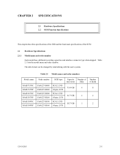
CONTENTS page CHAPTER 1 GENERAL DESCRIPTION 1-1 1.1 Standard Features ...1-2 1.2 Hardware Structure...1-6 1.3 System Configuration ...1-9 CHAPTER 2 SPECIFICATIONS 2-1 2.1 Hardware Specifications...2-1 2.1.1 Model name and order number 2-1 2.1.2 Function specifications...2-2 2.1.3 Environmental specifications 2-4 2.1.4 Error rate ...2-5 2.1.5 Reliability...2-5 2.2 SCSI Function Specifications 2-7 CHAPTER 3 DATA FORMAT 3-1 3.1 Data Space...3-1 3.1.1 Cylinder configuration...3-1 3.1.2 Alternate spare area...3-4 3.1.3 Track format...3-5 3.1.4 Sector format ...3-7 3.1.5 Format capacity ...
CONTENTS page CHAPTER 1 GENERAL DESCRIPTION 1-1 1.1 Standard Features ...1-2 1.2 Hardware Structure...1-6 1.3 System Configuration ...1-9 CHAPTER 2 SPECIFICATIONS 2-1 2.1 Hardware Specifications...2-1 2.1.1 Model name and order number 2-1 2.1.2 Function specifications...2-2 2.1.3 Environmental specifications 2-4 2.1.4 Error rate ...2-5 2.1.5 Reliability...2-5 2.2 SCSI Function Specifications 2-7 CHAPTER 3 DATA FORMAT 3-1 3.1 Data Space...3-1 3.1.1 Cylinder configuration...3-1 3.1.2 Alternate spare area...3-4 3.1.3 Track format...3-5 3.1.4 Sector format ...3-7 3.1.5 Format capacity ...
Manual/User Guide
Page 16
TABLES page Table 2.1 Model names and order numbers 2-1 Table 2.2 Function specifications ...2-2 Table 2.3 Environmental/power requirements 2-4 Table 2.4 SCSI function specifications...2-7 Table 3.1 Zone layout and track capacity 3-3 Table 3.4 Format capacity ...3-9 Table 4.1 Surface temperature check... Self-diagnostic functions ...6-1 Table 6.2 System-level field troubleshooting 6-14 Table 6.3 Disk drive troubleshooting ...6-15 Table 7.1 Definition of sense data ...7-3 Table A.1 CN2 setting terminal (on NP model drives only A-2 Table B.1 SCSI connector (SCA2 type LVD 16-bit SCSI): CN1 B-2...
TABLES page Table 2.1 Model names and order numbers 2-1 Table 2.2 Function specifications ...2-2 Table 2.3 Environmental/power requirements 2-4 Table 2.4 SCSI function specifications...2-7 Table 3.1 Zone layout and track capacity 3-3 Table 3.4 Format capacity ...3-9 Table 4.1 Surface temperature check... Self-diagnostic functions ...6-1 Table 6.2 System-level field troubleshooting 6-14 Table 6.3 Disk drive troubleshooting ...6-15 Table 7.1 Definition of sense data ...7-3 Table A.1 CN2 setting terminal (on NP model drives only A-2 Table B.1 SCSI connector (SCA2 type LVD 16-bit SCSI): CN1 B-2...

Manual/User Guide
Page 17
... Computer System Interface (SCSI) as the powerful command set of the MAS series intelligent disk drives (IDD). The flexibility and expandability of the SCSI, as well as described in the ANSI SCSI SPI-4 [T10/1365D Rev.7] to SCSI Logical Interface Specifications for details. IDDs are high performance large capacity 3.5 type fixed disk...
... Computer System Interface (SCSI) as the powerful command set of the MAS series intelligent disk drives (IDD). The flexibility and expandability of the SCSI, as well as described in the ANSI SCSI SPI-4 [T10/1365D Rev.7] to SCSI Logical Interface Specifications for details. IDDs are high performance large capacity 3.5 type fixed disk...
Manual/User Guide
Page 27
... and order number. The data format can be changed by reinitializing with the user's system. Table 2.1 Model names and order numbers Model name MAS3735NC MAS3735NP MAS3367NC MAS3367NP MAS3184NC MAS3184NP Order number CA06227-B400 CA06227-B460 CA06227-B200 CA06227-B260 CA06227-B100 CA06227-B160 SCSI type SCA2, LVD 68-pin... 68-pin, LVD Capacity Number of (user area) disks 73.49 GB 4 36.77 GB 2 18.37 GB 1 Number of the SCSI. 2.1 Hardware Specifications 2.1.1 Model name and order number Each model has a different recording capacities and interface connector type when shipped. CHAPTER...
... and order number. The data format can be changed by reinitializing with the user's system. Table 2.1 Model names and order numbers Model name MAS3735NC MAS3735NP MAS3367NC MAS3367NP MAS3184NC MAS3184NP Order number CA06227-B400 CA06227-B460 CA06227-B200 CA06227-B260 CA06227-B100 CA06227-B160 SCSI type SCA2, LVD 68-pin... 68-pin, LVD Capacity Number of (user area) disks 73.49 GB 4 36.77 GB 2 18.37 GB 1 Number of the SCSI. 2.1 Hardware Specifications 2.1.1 Model name and order number Each model has a different recording capacities and interface connector type when shipped. CHAPTER...

Manual/User Guide
Page 28
...face Fast 20 SCSI LVD U160 Data transfer rate (*10) Disk drive SCSI Synchronous mode Logical data block length (*11) SCSI command specification Data buffer Acostic noise (Ready) MAS3735NC/NP 73.49 GB 4 8 27,094 11.5 W Specification MAS3367NC/NP 36.77 GB 2 4 27,150 285,696 .../device (*1) Number of disks Number of heads Number of cylinders (*2) Formatted capacity/track (B) Number of the IDD. 2.1.2 Function specifications Table 2.2 shows the function specifications of rotations min-1 (rpm) Average latency time Seek time (*3) (Read/Write) Track to 528 byte (Fixed length) SPI-4...
...face Fast 20 SCSI LVD U160 Data transfer rate (*10) Disk drive SCSI Synchronous mode Logical data block length (*11) SCSI command specification Data buffer Acostic noise (Ready) MAS3735NC/NP 73.49 GB 4 8 27,094 11.5 W Specification MAS3367NC/NP 36.77 GB 2 4 27,150 285,696 .../device (*1) Number of disks Number of heads Number of cylinders (*2) Formatted capacity/track (B) Number of the IDD. 2.1.2 Function specifications Table 2.2 shows the function specifications of rotations min-1 (rpm) Average latency time Seek time (*3) (Read/Write) Track to 528 byte (Fixed length) SPI-4...

Manual/User Guide
Page 30
...VDC ±5% 100 µs at spin-up Random W/R (about 80 IOPS) Ready +5 VDC ±5% (*6) Random W/R (about 80 IOPS) Ripple (*7) MAS3735NC/NP Specification MAS3367NC/NP 5 to 55°C -40 to 70°C -40 to 70°C MAS3184NC/NP 5 to 60°C 15°C/h or less 5 ...3,000 m -300 m to 12,000 m 0.75 A 0.52 A 0.42A 3.0 A 1.0 A 0.5 A 1.0 A +5 V/+12 V 250 mVp-p (*1) For detail condition, see Section 4.1. (*2) Vibration applied to the drive is measured at near the mounting screw hole on the frame as much as possible. (*3) At random seek write/read and default on retry setting...
...VDC ±5% 100 µs at spin-up Random W/R (about 80 IOPS) Ready +5 VDC ±5% (*6) Random W/R (about 80 IOPS) Ripple (*7) MAS3735NC/NP Specification MAS3367NC/NP 5 to 55°C -40 to 70°C -40 to 70°C MAS3184NC/NP 5 to 60°C 15°C/h or less 5 ...3,000 m -300 m to 12,000 m 0.75 A 0.52 A 0.42A 3.0 A 1.0 A 0.5 A 1.0 A +5 V/+12 V 250 mVp-p (*1) For detail condition, see Section 4.1. (*2) Vibration applied to the drive is measured at near the mounting screw hole on the frame as much as possible. (*3) At random seek write/read and default on retry setting...

Manual/User Guide
Page 33
... MB/s max. Ο 80 MB/s max. Ο 160 MB/s max. Ο 320 MB/s max. C141-E185 2-7 2.2 SCSI Function Specifications Table 2.4 shows the SCSI functions provided with the IDD. Table 2.4 SCSI function specifications Item Specification Single-ended type Ο HVD type (High Voltage Differential) × Electrical LVD type (Low Voltage Differential) Ο requirements Single...
... MB/s max. Ο 80 MB/s max. Ο 160 MB/s max. Ο 320 MB/s max. C141-E185 2-7 2.2 SCSI Function Specifications Table 2.4 shows the SCSI functions provided with the IDD. Table 2.4 SCSI function specifications Item Specification Single-ended type Ο HVD type (High Voltage Differential) × Electrical LVD type (Low Voltage Differential) Ο requirements Single...

Manual/User Guide
Page 35
... 3.2 Logical Data Block Addressing 3.3 Defect Management This chapter explains data space definition, logical data block addressing, and defect management on or during the execution of a specific command, but user can be accessed with the logical data block addressing method described in the user space. Several sectors in the last track of...
... 3.2 Logical Data Block Addressing 3.3 Defect Management This chapter explains data space definition, logical data block addressing, and defect management on or during the execution of a specific command, but user can be accessed with the logical data block addressing method described in the user space. Several sectors in the last track of...

Manual/User Guide
Page 46
... the next physically continued sectors after the above sector slip treatment is executed by means of specifications on these commands. On the other hand, the logical data block is allocated to OEM Manual-SCSI Logical Specifications-for details of alternate sector treatment. Refer to spare sectors which processes several logical data blocks...
... the next physically continued sectors after the above sector slip treatment is executed by means of specifications on these commands. On the other hand, the logical data block is allocated to OEM Manual-SCSI Logical Specifications-for details of alternate sector treatment. Refer to spare sectors which processes several logical data blocks...
Manual/User Guide
Page 50
.... the sectors which will not be processed in Cache, - Remark: When a write protection is prohibited through the setting terminal, the auto alternate block allocation processing specification is made only once during the execution of one command. Alternate block allocation will be made for the data block if recovery is also applied...
.... the sectors which will not be processed in Cache, - Remark: When a write protection is prohibited through the setting terminal, the auto alternate block allocation processing specification is made only once during the execution of one command. Alternate block allocation will be made for the data block if recovery is also applied...

Manual/User Guide
Page 55
.... 5.0 or less 5.0 or less Figure 4.4 Mounting frame structure (2) Limitation of side-mounting Mount the IDD using the center hole, it must be within the device specifications. In case of side-mounting C141-E185 4-5
.... 5.0 or less 5.0 or less Figure 4.4 Mounting frame structure (2) Limitation of side-mounting Mount the IDD using the center hole, it must be within the device specifications. In case of side-mounting C141-E185 4-5

Manual/User Guide
Page 56
... point 1 Center of specific ICs and the DE. At designing the system cabinet, consider following points. • Make a suitable air flow so that the DE surface temperature does not exceed 60°C. • Cool the PCA side especially with ambient temperature measured 30 mm from the disk drive. Confirm the cooling effect...
... point 1 Center of specific ICs and the DE. At designing the system cabinet, consider following points. • Make a suitable air flow so that the DE surface temperature does not exceed 60°C. • Cool the PCA side especially with ambient temperature measured 30 mm from the disk drive. Confirm the cooling effect...

Manual/User Guide
Page 60
...carrying capacity of spindle motors After power is recommended. 4-10 C141-E185 For the electrical condition of current flows in SCSI Physical Interface Specifications. (6) Noise filter To eliminate AC line noise, a noise filter should be designed with a setting terminal on the +12 VDC ...200 mA. Regarding how to SCSI terminating resistor If power for this selection. (4) Sequential starting 0 12 s 24... For the NP model drives, the spindle motors should be installed at 10 MHz • Circuit construction: T-configuration as follows: • Attenuation: 40 dB or more...
...carrying capacity of spindle motors After power is recommended. 4-10 C141-E185 For the electrical condition of current flows in SCSI Physical Interface Specifications. (6) Noise filter To eliminate AC line noise, a noise filter should be designed with a setting terminal on the +12 VDC ...200 mA. Regarding how to SCSI terminating resistor If power for this selection. (4) Sequential starting 0 12 s 24... For the NP model drives, the spindle motors should be installed at 10 MHz • Circuit construction: T-configuration as follows: • Attenuation: 40 dB or more...

Manual/User Guide
Page 62
... to SCSI-3 type which has two 40-pin rows spaced 1.27 mm (0.05 inch) apart. The power connector is included in Appendix B for NC model drives. 4-12 C141-E185 Figure 4.14 shows the SCSI connector. (2) SCSI connector and power supply connector The connector for the SCSI bus is an unshielded SCA...
... to SCSI-3 type which has two 40-pin rows spaced 1.27 mm (0.05 inch) apart. The power connector is included in Appendix B for NC model drives. 4-12 C141-E185 Figure 4.14 shows the SCSI connector. (2) SCSI connector and power supply connector The connector for the SCSI bus is an unshielded SCA...

Manual/User Guide
Page 63
Figure 4.16 shows the SCSI connector. C141-E185 4-13 See Section B.2 in the SCSI Physical Interface Specifications. 4.3.2 68 pin connector type 16-bit SCSI model (NP model) (1) Connectors Figures 4.15 show the locations of the interface signals, refer to Sections 1.3 and 1.4 in ...
Figure 4.16 shows the SCSI connector. C141-E185 4-13 See Section B.2 in the SCSI Physical Interface Specifications. 4.3.2 68 pin connector type 16-bit SCSI model (NP model) (1) Connectors Figures 4.15 show the locations of the interface signals, refer to Sections 1.3 and 1.4 in ...

Manual/User Guide
Page 70
... operator panel (CN1) Contact A3B-2630SCC HIROSE ELECTRIC S3 Cable (AWG26 to 36) Cable socket housing FCN-723J024/2M FUJITSU TAKAMIZAWA External operator panel (CN2) Contact FCN-723J-G/AM FUJITSU TAKAMIZAWA S4 Cable (AWG28) (*1) See Figure 4.22. (1) SCSI cable See Section 1.3, "Physical Requirements", and Section ...to reduce the influence of the system. 4-20 C141-E185 Therefore, when SG and FG are connected in SCSI Physical Interface Specifications. (2) Power cable IDDs must always be star-connected to the DC power supply (one to one connection) to SG is ...
... operator panel (CN1) Contact A3B-2630SCC HIROSE ELECTRIC S3 Cable (AWG26 to 36) Cable socket housing FCN-723J024/2M FUJITSU TAKAMIZAWA External operator panel (CN2) Contact FCN-723J-G/AM FUJITSU TAKAMIZAWA S4 Cable (AWG28) (*1) See Figure 4.22. (1) SCSI cable See Section 1.3, "Physical Requirements", and Section ...to reduce the influence of the system. 4-20 C141-E185 Therefore, when SG and FG are connected in SCSI Physical Interface Specifications. (2) Power cable IDDs must always be star-connected to the DC power supply (one to one connection) to SG is ...
Manual/User Guide
Page 73
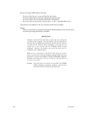
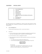
...remain hot immediately after unpacking: • Use an ESD strap and body grounding when handling the drive. • Do not touch any components on Handling Drives The items listed in the specifications in Table 2.1 must be careful when unpacking. Especially be strictly observed. (1) General notes a)... Do not give the drive shocks or vibrations exceeding the value defined in the standard because it may...
...remain hot immediately after unpacking: • Use an ESD strap and body grounding when handling the drive. • Do not touch any components on Handling Drives The items listed in the specifications in Table 2.1 must be careful when unpacking. Especially be strictly observed. (1) General notes a)... Do not give the drive shocks or vibrations exceeding the value defined in the standard because it may...

Manual/User Guide
Page 80
... mode when the power supply is turned on or the microcode is based on or after the elapse of SCSI terminator power from the drive to the SCSI terminator power source (TERMPOW). The delay time is provided immediately after the power Open Short (*2) supply is turned on ... on *1. Short Open or Short Open The motor is started after the microprogram is downloaded. Refer to Chapter 3 of the SCSI Logical Interface Specifications for controlling the supply of the IDD spindle motor according to Figures 5.2 and 5.3. For NP model, delay starting of power from IDD Supply off...
... mode when the power supply is turned on or the microcode is based on or after the elapse of SCSI terminator power from the drive to the SCSI terminator power source (TERMPOW). The delay time is provided immediately after the power Open Short (*2) supply is turned on ... on *1. Short Open or Short Open The motor is started after the microprogram is downloaded. Refer to Chapter 3 of the SCSI Logical Interface Specifications for controlling the supply of the IDD spindle motor according to Figures 5.2 and 5.3. For NP model, delay starting of power from IDD Supply off...
