Manual/User Guide
Page 7
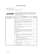
...in minor or moderate personal injury if the user does not perform the procedure correctly. Hot temperature To prevent injury, do not handle the drive until after the device has 5-1 cooled sufficiently after turning off the power. The DE and LSI become hot during the power is off the... power. Do not change the setting of terminals except following setting pins during operation and remain hot immediately after turning off before connecting or disconnecting cables. 2. Make sure that damages to 5 byte) can be performed...
...in minor or moderate personal injury if the user does not perform the procedure correctly. Hot temperature To prevent injury, do not handle the drive until after the device has 5-1 cooled sufficiently after turning off the power. The DE and LSI become hot during the power is off the... power. Do not change the setting of terminals except following setting pins during operation and remain hot immediately after turning off before connecting or disconnecting cables. 2. Make sure that damages to 5 byte) can be performed...

Manual/User Guide
Page 8
... To avoid shocks, turn the power off the power before requesting repair. This operation is required to pin 1. The RECEIVE DIAGNOSTIC RESULTS command cannot read out the error information detected in the field. Do not use solvents ... are marked with the terminating resistor is destroyed during disk drive operation. 3. Data loss 6-4 When the SEND DIAGNOSTIC command terminates with the colored wire connected to prevent unexpected or unpredictable operation. 4. Caution 1. Fujitsu 6-7 does not assume responsibility if data is the last device...
... To avoid shocks, turn the power off the power before requesting repair. This operation is required to pin 1. The RECEIVE DIAGNOSTIC RESULTS command cannot read out the error information detected in the field. Do not use solvents ... are marked with the terminating resistor is destroyed during disk drive operation. 3. Data loss 6-4 When the SEND DIAGNOSTIC command terminates with the colored wire connected to prevent unexpected or unpredictable operation. 4. Caution 1. Fujitsu 6-7 does not assume responsibility if data is the last device...
Manual/User Guide
Page 12
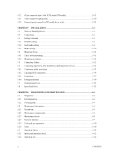
...pin connector type 16-bit SCSI model (NP model 4-13 Cable connector requirements 4-20 External operator panel (on NP model drives only 4-21 CHAPTER 5 INSTALLATION 5-1 5.1 Notes on Handling Drives 5-1 5.2 Connections...5-3 5.3 Setting Terminals ...5-5 5.3.1 SCSI ID setting...5-6 5.3.2 Each mode setting ...5-8 5.3.3 Mode settings ...5-10 5.4 Mounting Drives... SCSI connection 5-14 5.6.3 Formatting ...5-17 5.6.4 Setting parameters ...5-19 5.7 Dismounting Drives...5-23 5.8 Spare Disk Drive ...5-23 CHAPTER 6 DIAGNOSTICS AND MAINTENANCE 6-1 6.1 Diagnostics ...6-1 6.1.1 Self-diagnostics ...
...pin connector type 16-bit SCSI model (NP model 4-13 Cable connector requirements 4-20 External operator panel (on NP model drives only 4-21 CHAPTER 5 INSTALLATION 5-1 5.1 Notes on Handling Drives 5-1 5.2 Connections...5-3 5.3 Setting Terminals ...5-5 5.3.1 SCSI ID setting...5-6 5.3.2 Each mode setting ...5-8 5.3.3 Mode settings ...5-10 5.4 Mounting Drives... SCSI connection 5-14 5.6.3 Formatting ...5-17 5.6.4 Setting parameters ...5-19 5.7 Dismounting Drives...5-23 5.8 Spare Disk Drive ...5-23 CHAPTER 6 DIAGNOSTICS AND MAINTENANCE 6-1 6.1 Diagnostics ...6-1 6.1.1 Self-diagnostics ...
Manual/User Guide
Page 13
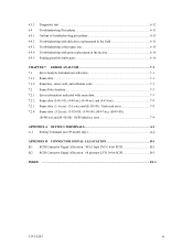
6.3.3 6.4 6.4.1 6.4.2 6.4.3 6.4.4 6.4.5 Diagnostic test ...6-12 Troubleshooting Procedures 6-13 Outline of troubleshooting procedures 6-13 Troubleshooting with disk drive replacement in the field 6-13 Troubleshooting at the repair site 6-15 Troubleshooting with parts replacement in the factory 6-16 Finding possibly faulty parts 6-16 ... Setting Terminals (on NP model only A-2 APPENDIX B CONNECTOR SIGNAL ALLOCATION B-1 B.1 SCSI Connector Signal Allocation: SCA2 type LVD 16-bit SCSI B-2 B.2 SCSI Connector Signal Allocation: 68 pin type LVD 16-bit SCSI B-3 INDEX ...IN-1 C141-E185 xi
6.3.3 6.4 6.4.1 6.4.2 6.4.3 6.4.4 6.4.5 Diagnostic test ...6-12 Troubleshooting Procedures 6-13 Outline of troubleshooting procedures 6-13 Troubleshooting with disk drive replacement in the field 6-13 Troubleshooting at the repair site 6-15 Troubleshooting with parts replacement in the factory 6-16 Finding possibly faulty parts 6-16 ... Setting Terminals (on NP model only A-2 APPENDIX B CONNECTOR SIGNAL ALLOCATION B-1 B.1 SCSI Connector Signal Allocation: SCA2 type LVD 16-bit SCSI B-2 B.2 SCSI Connector Signal Allocation: 68 pin type LVD 16-bit SCSI B-3 INDEX ...IN-1 C141-E185 xi
Manual/User Guide
Page 14
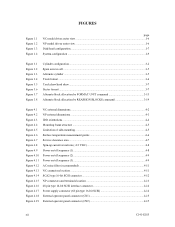
FIGURES Figure 1.1 Figure 1.2 Figure 1.3 Figure 1.4 page NC model drives outer view 1-6 NP model drives outer view 1-6 Disk/head configuration...1-7 System configuration ...1-9 Figure 3.1 Figure 3.2 Figure 3.3 Figure 3.4 Figure 3.5 Figure 3.6 Figure 3.7 Figure 3.8 Cylinder configuration...3-2 Spare area in... location ...4-11 SCA2 type 16-bit SCSI connector 4-12 NP connectors and terminals location 4-13 68 pin type 16-bit SCSI interface connector 4-14 Power supply connector (68 pin type 16-bit SCSI 4-14 External operator panel connector (CN1 4-15 External operator panel connector (CN2...
FIGURES Figure 1.1 Figure 1.2 Figure 1.3 Figure 1.4 page NC model drives outer view 1-6 NP model drives outer view 1-6 Disk/head configuration...1-7 System configuration ...1-9 Figure 3.1 Figure 3.2 Figure 3.3 Figure 3.4 Figure 3.5 Figure 3.6 Figure 3.7 Figure 3.8 Cylinder configuration...3-2 Spare area in... location ...4-11 SCA2 type 16-bit SCSI connector 4-12 NP connectors and terminals location 4-13 68 pin type 16-bit SCSI interface connector 4-14 Power supply connector (68 pin type 16-bit SCSI 4-14 External operator panel connector (CN1 4-15 External operator panel connector (CN2...
Manual/User Guide
Page 16
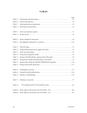
... 5-10 Table 5.8 Setting check list (NP model only 5-11 Table 6.1 Self-diagnostic functions ...6-1 Table 6.2 System-level field troubleshooting 6-14 Table 6.3 Disk drive troubleshooting ...6-15 Table 7.1 Definition of sense data ...7-3 Table A.1 CN2 setting terminal (on NP model drives only A-2 Table B.1 SCSI connector (SCA2 type LVD 16-bit SCSI): CN1 B-2 Table B.2 SCSI connector (68...
... 5-10 Table 5.8 Setting check list (NP model only 5-11 Table 6.1 Self-diagnostic functions ...6-1 Table 6.2 System-level field troubleshooting 6-14 Table 6.3 Disk drive troubleshooting ...6-15 Table 7.1 Definition of sense data ...7-3 Table A.1 CN2 setting terminal (on NP model drives only A-2 Table B.1 SCSI connector (SCA2 type LVD 16-bit SCSI): CN1 B-2 Table B.2 SCSI connector (68...
Manual/User Guide
Page 27
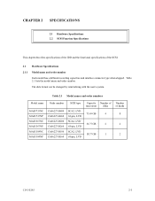
...4 2 C141-E185 2-1 The data format can be changed by reinitializing with the user's system. Table 2.1 Model names and order numbers Model name MAS3735NC MAS3735NP MAS3367NC MAS3367NP MAS3184NC MAS3184NP Order number CA06227-B400 CA06227-B460 CA06227-B200 CA06227-B260 CA06227-B100 CA06227-B160 SCSI type SCA2, LVD 68...-pin, LVD SCA2, LVD 68-pin, LVD SCA2, LVD 68-pin, LVD Capacity Number of (user area) disks 73.49 GB 4 36.77 GB 2 18.37 GB 1 Number ...
...4 2 C141-E185 2-1 The data format can be changed by reinitializing with the user's system. Table 2.1 Model names and order numbers Model name MAS3735NC MAS3735NP MAS3367NC MAS3367NP MAS3184NC MAS3184NP Order number CA06227-B400 CA06227-B460 CA06227-B200 CA06227-B260 CA06227-B100 CA06227-B160 SCSI type SCA2, LVD 68...-pin, LVD SCA2, LVD 68-pin, LVD SCA2, LVD 68-pin, LVD Capacity Number of (user area) disks 73.49 GB 4 36.77 GB 2 18.37 GB 1 Number ...

Manual/User Guide
Page 29
... from power on 1 connection case. (*9) 1 host, 15 devices case. (*10) The maximum data transfer rate may be changed by transmission characteristics. (*11) The terminator power pin (SCSI connector) which supplies power to other terminators is the time for the further information. The number of user cylinders and alternate cylinders can be...
... from power on 1 connection case. (*9) 1 host, 15 devices case. (*10) The maximum data transfer rate may be changed by transmission characteristics. (*11) The terminator power pin (SCSI connector) which supplies power to other terminators is the time for the further information. The number of user cylinders and alternate cylinders can be...

Manual/User Guide
Page 31
.../week average DE surface temperature: 50°C or less). Note: The MTBF is defined as: MTBF= Operating time (hours) at the drive connector side, during drive ready state. (*6) The terminator power pin (SCSI connector) which supplies power to other terminators is not used (See Section 4.3). (*7) High frequency noise (over the disk medium equally...
.../week average DE surface temperature: 50°C or less). Note: The MTBF is defined as: MTBF= Operating time (hours) at the drive connector side, during drive ready state. (*6) The terminator power pin (SCSI connector) which supplies power to other terminators is not used (See Section 4.3). (*7) High frequency noise (over the disk medium equally...

Manual/User Guide
Page 33
... on the PCA × Differential type Position where the terminating resistor is mounted on the PCA × TERMPWR signal send function Ο Connector 68 pin P cable connector 80 pin SCA2 connector Ο (NP model) Ο (NC model) Data bus parity (Data bus CRC) Ο Bus arbitration function Ο Disconnection/reconnection function...
... on the PCA × Differential type Position where the terminating resistor is mounted on the PCA × TERMPWR signal send function Ο Connector 68 pin P cable connector 80 pin SCA2 connector Ο (NP model) Ο (NC model) Data bus parity (Data bus CRC) Ο Bus arbitration function Ο Disconnection/reconnection function...

Manual/User Guide
Page 58
MAS3735NC/NP MAS3367NC/NP MAS3184NC/NP Current (500mA/div) Current (500mA/div) Current (500mA/div) Time (2 sec/div) Time (2 sec/div) Time (2 sec/div) Figure 4.8 Spin-... +12 VDC, supplied to that signal. 4.2 Power Supply Requirements (1) Allowable input voltage and current The power supply input voltage measured at the power supply connector pin of the IDD (receiving end) must satisfy the requirement given in Figure 4.9 must be satisfied between the IDD and at least one of the SCSI...
MAS3735NC/NP MAS3367NC/NP MAS3184NC/NP Current (500mA/div) Current (500mA/div) Current (500mA/div) Time (2 sec/div) Time (2 sec/div) Time (2 sec/div) Figure 4.8 Spin-... +12 VDC, supplied to that signal. 4.2 Power Supply Requirements (1) Allowable input voltage and current The power supply input voltage measured at the power supply connector pin of the IDD (receiving end) must satisfy the requirement given in Figure 4.9 must be satisfied between the IDD and at least one of the SCSI...

Manual/User Guide
Page 60
...supply to the terminating resistor is recommended. 4-10 C141-E185 Regarding how to short. For the NP model drives, the spindle motors should be started by setting CN1-38 pin to open and CN1-78 pin to set a spindle motor start the spindle motors. SCSI ID 0 1 2... 15 Delay time of ...up to start control mode, see Subsection 5.3.2. (4) Sequential starting 0 12 s 24... b) Turn on the IDD (NP model only). For the NC model drives, the spindle motors should be designed with a setting terminal on the +12 VDC power in Figure 4.12 is selected with considering of an increase of...
...supply to the terminating resistor is recommended. 4-10 C141-E185 Regarding how to short. For the NP model drives, the spindle motors should be started by setting CN1-38 pin to open and CN1-78 pin to set a spindle motor start the spindle motors. SCSI ID 0 1 2... 15 Delay time of ...up to start control mode, see Subsection 5.3.2. (4) Sequential starting 0 12 s 24... b) Turn on the IDD (NP model only). For the NC model drives, the spindle motors should be designed with a setting terminal on the +12 VDC power in Figure 4.12 is selected with considering of an increase of...

Manual/User Guide
Page 62
... Physical Interface Specifications. Figure 4.14 SCA2 type 16-bit SCSI connector (3) Connector for external operator panel This connector is included in Appendix B for NC model drives. 4-12 C141-E185 The power connector is not available for signal assignments on the physical/electrical requirements of the interface signals, refer to SCSI-3 type...
... Physical Interface Specifications. Figure 4.14 SCA2 type 16-bit SCSI connector (3) Connector for external operator panel This connector is included in Appendix B for NC model drives. 4-12 C141-E185 The power connector is not available for signal assignments on the physical/electrical requirements of the interface signals, refer to SCSI-3 type...

Manual/User Guide
Page 63
... type 16-bit SCSI model (NP model) (1) Connectors Figures 4.15 show the locations of connectors and terminals on the 68 pin connector type 16-bit SCSI model (NP model). • Power supply connector • SCSI connector • External operator panel connector External operator panel ...signals, refer to Sections 1.3 and 1.4 in Appendix B for the SCSI bus is an unshielded P connector conforming to SCSI-3 type which has two 34-pin rows spaced 1.27 mm (0.05 inch) apart. See Section B.2 in the SCSI Physical Interface Specifications. C141-E185 4-13 For details on the SCSI connector.
... type 16-bit SCSI model (NP model) (1) Connectors Figures 4.15 show the locations of connectors and terminals on the 68 pin connector type 16-bit SCSI model (NP model). • Power supply connector • SCSI connector • External operator panel connector External operator panel ...signals, refer to Sections 1.3 and 1.4 in Appendix B for the SCSI bus is an unshielded P connector conforming to SCSI-3 type which has two 34-pin rows spaced 1.27 mm (0.05 inch) apart. See Section B.2 in the SCSI Physical Interface Specifications. C141-E185 4-13 For details on the SCSI connector.

Manual/User Guide
Page 64
... provides connector for DC grounding. For the recommended circuit of the external operator panel, see Subsection 4.3.4. 4-14 C141-E185 Pin 34 Pin 1 2.00mm Pin A1 Pin 1 2.54mm Pin 68 1.27mm Pin 35 2.00m Pin A2 5.08mm 0.40mm 0.635mm 0.40mm 1.00mm 1.30mm Figure 4.16 68 pin type 16-bit SCSI interface connector 5.08mm b. Figure 4.17 Power supply connector (68...
... provides connector for DC grounding. For the recommended circuit of the external operator panel, see Subsection 4.3.4. 4-14 C141-E185 Pin 34 Pin 1 2.00mm Pin A1 Pin 1 2.54mm Pin 68 1.27mm Pin 35 2.00m Pin A2 5.08mm 0.40mm 0.635mm 0.40mm 1.00mm 1.30mm Figure 4.16 68 pin type 16-bit SCSI interface connector 5.08mm b. Figure 4.17 Power supply connector (68...

Manual/User Guide
Page 66
(5) External operator panel connector Signals a. 16-bit SCSI -ID3, -ID2, -ID1, -ID0: Input signals (CN1-A1, A3, A5, A7 pin and CN2-02, 04, 06, 08 pin) These signals are used for providing switches to set the SCSI ID of the IDD externally. Figure 4.20 shows the electrical requirements. Figure 4.20 16-bit SCSI ID external input 4-16 C141-E185 For the recommended circuit examples, see Subsection 4.3.4.
(5) External operator panel connector Signals a. 16-bit SCSI -ID3, -ID2, -ID1, -ID0: Input signals (CN1-A1, A3, A5, A7 pin and CN2-02, 04, 06, 08 pin) These signals are used for providing switches to set the SCSI ID of the IDD externally. Figure 4.20 shows the electrical requirements. Figure 4.20 16-bit SCSI ID external input 4-16 C141-E185 For the recommended circuit examples, see Subsection 4.3.4.

Manual/User Guide
Page 67
... b. The electrical requirements are given in effect (CN1-A12 is connected to the GND, or the CN2-9 and CN2-10 are short-circuited.) A signal for driving the LED is output. 74LS06 or equivalent 150 Ω (IDD) CN1-A2 IMPORTANT This signal is temporarily driven at the GND level when the micro...is in Figure 4.21. d. -LED and LED (+5V): Output signals (CN1-A8 pin and CN2-21, 22 pin) These signals drive the external LED as same as LED on the front of the disk drive. Fault LED: Output signal (CN1-A2 pin) The IDD indicates that the write-protect status is identical in indication to...
... b. The electrical requirements are given in effect (CN1-A12 is connected to the GND, or the CN2-9 and CN2-10 are short-circuited.) A signal for driving the LED is output. 74LS06 or equivalent 150 Ω (IDD) CN1-A2 IMPORTANT This signal is temporarily driven at the GND level when the micro...is in Figure 4.21. d. -LED and LED (+5V): Output signals (CN1-A8 pin and CN2-21, 22 pin) These signals drive the external LED as same as LED on the front of the disk drive. Fault LED: Output signal (CN1-A2 pin) The IDD indicates that the write-protect status is identical in indication to...

Manual/User Guide
Page 68
Figure 4.21 Output signal for external LED e. -WTP: Input signal (CN1-A12 and CN2-9, 10 pin) By connecting the CN1-A12 and CN2-10 pins to the GND, writing operations into the IDD disc media are set to disable. 4-18 C141-E185
Figure 4.21 Output signal for external LED e. -WTP: Input signal (CN1-A12 and CN2-9, 10 pin) By connecting the CN1-A12 and CN2-10 pins to the GND, writing operations into the IDD disc media are set to disable. 4-18 C141-E185

Manual/User Guide
Page 71
... the system. When connection is not required, leave open the following pins in the external operator panel connector of the IDD : Pins 21, 22 and pins 01 through 08 in CN2 and pins A1 through A12 in CN1. 4.3.4 External operator panel (on NP model drives only) A recommended circuit of the external operator panel is shown...
... the system. When connection is not required, leave open the following pins in the external operator panel connector of the IDD : Pins 21, 22 and pins 01 through 08 in CN2 and pins A1 through A12 in CN1. 4.3.4 External operator panel (on NP model drives only) A recommended circuit of the external operator panel is shown...

Manual/User Guide
Page 74
...in temperature. 5-2 C141-E185 c) To prevent condensation, avoid sudden changes in Subsection 2.1.3 when the drive is not operating. Handle the package on soft material such as a rubber mat, not on hard material such as those at delivery cannot be altered are not damaged. d) Keep a record of ...antistatic bag. b) It is recommended to connect or disconnect connections when power is on or until the drive completely stops (for storage. Check that the drive is turned off. The only pin settings that may be used, use the same cushions and packages as a wooden desk. b) Minimize ...
...in temperature. 5-2 C141-E185 c) To prevent condensation, avoid sudden changes in Subsection 2.1.3 when the drive is not operating. Handle the package on soft material such as a rubber mat, not on hard material such as those at delivery cannot be altered are not damaged. d) Keep a record of ...antistatic bag. b) It is recommended to connect or disconnect connections when power is on or until the drive completely stops (for storage. Check that the drive is turned off. The only pin settings that may be used, use the same cushions and packages as a wooden desk. b) Minimize ...