Manual/User Guide
Page 5
... 6 DIAGNOSIS AND MAINTENANCE This chapter describes the automatic diagnosis, and maintenance of interface connector. PREFACE This manual describes the MAS3735NC/NP, MAS3367NC/NP and MAS3184NC/NP (hereafter, MAS series), 3.5 type fixed disk drives with an embedded SCSI controller. CHAPTER 5 INSTALLATION This chapter explains how to do about media defects. CHAPTER 7 ERROR ANALYSIS This chapter describes...
... 6 DIAGNOSIS AND MAINTENANCE This chapter describes the automatic diagnosis, and maintenance of interface connector. PREFACE This manual describes the MAS3735NC/NP, MAS3367NC/NP and MAS3184NC/NP (hereafter, MAS series), 3.5 type fixed disk drives with an embedded SCSI controller. CHAPTER 5 INSTALLATION This chapter explains how to do about media defects. CHAPTER 7 ERROR ANALYSIS This chapter describes...
Manual/User Guide
Page 6
... to users or by standards. Hexadecimal number is represented normally. CONVENTIONS USED IN THIS MANUAL The MAS3735NC/NP, MAS3367NC/NP and MAS3184NC/NP disk drives are needed. iv C141-E185 Binary number is represented as "the intelligent disk drive (IDD)", "the drive" or "the device" in the sheet. To make this manual. CONVENTIONS FOR ALERT MESSAGES This...
... to users or by standards. Hexadecimal number is represented normally. CONVENTIONS USED IN THIS MANUAL The MAS3735NC/NP, MAS3367NC/NP and MAS3184NC/NP disk drives are needed. iv C141-E185 Binary number is represented as "the intelligent disk drive (IDD)", "the drive" or "the device" in the sheet. To make this manual. CONVENTIONS FOR ALERT MESSAGES This...
Manual/User Guide
Page 7
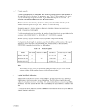
...the user does not perform the procedure correctly. The DE and LSI become hot during the power is on . • Write protect: CN2 9-10 (NP model only) 3. The user must not change setting status set at factory shipment. 2. To short the setting terminal, use the short plug attached when... connect or disconnect cables when power is turned on . (except NC model) C141-E185 v Hot temperature To prevent injury, do not handle the drive until after the device has 5-1 cooled sufficiently after turning off the power. Do not change the setting of read sector keeps allowable error byte number...
...the user does not perform the procedure correctly. The DE and LSI become hot during the power is on . • Write protect: CN2 9-10 (NP model only) 3. The user must not change setting status set at factory shipment. 2. To short the setting terminal, use the short plug attached when... connect or disconnect cables when power is turned on . (except NC model) C141-E185 v Hot temperature To prevent injury, do not handle the drive until after the device has 5-1 cooled sufficiently after turning off the power. Do not change the setting of read sector keeps allowable error byte number...
Manual/User Guide
Page 12
...NP model 4-13 Cable connector requirements 4-20 External operator panel (on NP model drives only 4-21 CHAPTER 5 INSTALLATION 5-1 5.1 Notes on Handling Drives 5-1 5.2 Connections...5-3 5.3 Setting Terminals ...5-5 5.3.1 SCSI ID setting...5-6 5.3.2 Each mode setting ...5-8 5.3.3 Mode settings ...5-10 5.4 Mounting Drives...5-13 5.6.2 Checking SCSI connection 5-14 5.6.3 Formatting ...5-17 5.6.4 Setting parameters ...5-19 5.7 Dismounting Drives...5-23 5.8 Spare Disk Drive ...5-23 CHAPTER 6 DIAGNOSTICS AND MAINTENANCE 6-1 6.1 Diagnostics ...6-1 6.1.1 Self-diagnostics ...6-1 6.1.2 Test programs...
...NP model 4-13 Cable connector requirements 4-20 External operator panel (on NP model drives only 4-21 CHAPTER 5 INSTALLATION 5-1 5.1 Notes on Handling Drives 5-1 5.2 Connections...5-3 5.3 Setting Terminals ...5-5 5.3.1 SCSI ID setting...5-6 5.3.2 Each mode setting ...5-8 5.3.3 Mode settings ...5-10 5.4 Mounting Drives...5-13 5.6.2 Checking SCSI connection 5-14 5.6.3 Formatting ...5-17 5.6.4 Setting parameters ...5-19 5.7 Dismounting Drives...5-23 5.8 Spare Disk Drive ...5-23 CHAPTER 6 DIAGNOSTICS AND MAINTENANCE 6-1 6.1 Diagnostics ...6-1 6.1.1 Self-diagnostics ...6-1 6.1.2 Test programs...
Manual/User Guide
Page 13
...6.4.2 6.4.3 6.4.4 6.4.5 Diagnostic test ...6-12 Troubleshooting Procedures 6-13 Outline of troubleshooting procedures 6-13 Troubleshooting with disk drive replacement in the field 6-13 Troubleshooting at the repair site 6-15 Troubleshooting with parts replacement in the factory ...-00), (B-47-xx), (B-49-00), (B-4D-xx) and (B-4E-00): SCSI interface error 7-4 APPENDIX A SETTING TERMINALS A-1 A.1 Setting Terminals (on NP model only A-2 APPENDIX B CONNECTOR SIGNAL ALLOCATION B-1 B.1 SCSI Connector Signal Allocation: SCA2 type LVD 16-bit SCSI B-2 B.2 SCSI Connector Signal Allocation: 68 ...
...6.4.2 6.4.3 6.4.4 6.4.5 Diagnostic test ...6-12 Troubleshooting Procedures 6-13 Outline of troubleshooting procedures 6-13 Troubleshooting with disk drive replacement in the field 6-13 Troubleshooting at the repair site 6-15 Troubleshooting with parts replacement in the factory ...-00), (B-47-xx), (B-49-00), (B-4D-xx) and (B-4E-00): SCSI interface error 7-4 APPENDIX A SETTING TERMINALS A-1 A.1 Setting Terminals (on NP model only A-2 APPENDIX B CONNECTOR SIGNAL ALLOCATION B-1 B.1 SCSI Connector Signal Allocation: SCA2 type LVD 16-bit SCSI B-2 B.2 SCSI Connector Signal Allocation: 68 ...
Manual/User Guide
Page 14
FIGURES Figure 1.1 Figure 1.2 Figure 1.3 Figure 1.4 page NC model drives outer view 1-6 NP model drives outer view 1-6 Disk/head configuration...1-7 System configuration ...1-9 Figure 3.1 Figure 3.2 Figure 3.3 Figure 3.4 Figure 3.5 Figure 3.6 Figure 3.7 Figure... 4.11 Figure 4.12 Figure 4.13 Figure 4.14 Figure 4.15 Figure 4.16 Figure 4.17 Figure 4.18 Figure 4.19 NC external dimensions...4-2 NP external dimensions ...4-3 IDD orientations ...4-4 Mounting frame structure ...4-5 Limitation of side-mounting 4-5 Surface temperature measurement points 4-6 Service clearance area ...4-7 Spin-...
FIGURES Figure 1.1 Figure 1.2 Figure 1.3 Figure 1.4 page NC model drives outer view 1-6 NP model drives outer view 1-6 Disk/head configuration...1-7 System configuration ...1-9 Figure 3.1 Figure 3.2 Figure 3.3 Figure 3.4 Figure 3.5 Figure 3.6 Figure 3.7 Figure... 4.11 Figure 4.12 Figure 4.13 Figure 4.14 Figure 4.15 Figure 4.16 Figure 4.17 Figure 4.18 Figure 4.19 NC external dimensions...4-2 NP external dimensions ...4-3 IDD orientations ...4-4 Mounting frame structure ...4-5 Limitation of side-mounting 4-5 Surface temperature measurement points 4-6 Service clearance area ...4-7 Spin-...

Manual/User Guide
Page 15
... SCSI cables connection ...4-19 External operator panel circuit example 4-21 Figure 5.1 Figure 5.2 Figure 5.3 Figure 5.4 Figure 5.5 SCSI bus connections ...5-4 Setting terminals location (on NP models only 5-5 CN2 setting terminal (on NP models only 5-6 Checking the SCSI connection (A 5-15 Checking the SCSI connection (B 5-16 Figure 6.1 Figure 6.2 Figure 6.3 Revision label ...6-9 Indicating revision numbers 6-10 Test...
... SCSI cables connection ...4-19 External operator panel circuit example 4-21 Figure 5.1 Figure 5.2 Figure 5.3 Figure 5.4 Figure 5.5 SCSI bus connections ...5-4 Setting terminals location (on NP models only 5-5 CN2 setting terminal (on NP models only 5-6 Checking the SCSI connection (A 5-15 Checking the SCSI connection (B 5-16 Figure 6.1 Figure 6.2 Figure 6.3 Revision label ...6-9 Indicating revision numbers 6-10 Test...
Manual/User Guide
Page 16
... only 5-11 Table 6.1 Self-diagnostic functions ...6-1 Table 6.2 System-level field troubleshooting 6-14 Table 6.3 Disk drive troubleshooting ...6-15 Table 7.1 Definition of sense data ...7-3 Table A.1 CN2 setting terminal (on NP model drives only A-2 Table B.1 SCSI connector (SCA2 type LVD 16-bit SCSI): CN1 B-2 Table B.2 SCSI connector (68 pin type LVD 16-bit SCSI): CN1 B-3 xiv...
... only 5-11 Table 6.1 Self-diagnostic functions ...6-1 Table 6.2 System-level field troubleshooting 6-14 Table 6.3 Disk drive troubleshooting ...6-15 Table 7.1 Definition of sense data ...7-3 Table A.1 CN2 setting terminal (on NP model drives only A-2 Table B.1 SCSI connector (SCA2 type LVD 16-bit SCSI): CN1 B-2 Table B.2 SCSI connector (68 pin type LVD 16-bit SCSI): CN1 B-3 xiv...

Manual/User Guide
Page 18
...paced transfer synchronous mode. 1-2 C141-E185 The IDD can manipulate data through logical block addressing regardless of the physical characteristics of the disk drive. For the ultra SCSI model, number of connectable SCSI devices on the same SCSI bus is varied as follows. • 8-bit SCSI...: 8 drives max. (option for NP model) • 16-bit SCSI: 16 drives max. (4) High speed data transfer Such a high data transfer rate on the SCSI bus can be connected directly to accommodate ...
...paced transfer synchronous mode. 1-2 C141-E185 The IDD can manipulate data through logical block addressing regardless of the physical characteristics of the disk drive. For the ultra SCSI model, number of connectable SCSI devices on the same SCSI bus is varied as follows. • 8-bit SCSI...: 8 drives max. (option for NP model) • 16-bit SCSI: 16 drives max. (4) High speed data transfer Such a high data transfer rate on the SCSI bus can be connected directly to accommodate ...

Manual/User Guide
Page 22
1.2 Hardware Structure An outer view of the controller. The IDD is composed of the disk, head, spindle motor, mounted disk enclosure (DE) with actuator and air circulation filter, as well as read/write pre-amp with the printed circuit assembly (PCA) of the IDD is given in Figures 1.1 and 1.2. Figure 1.1 NC model drives outer view Figure 1.2 NP model drives outer view 1-6 C141-E185
1.2 Hardware Structure An outer view of the controller. The IDD is composed of the disk, head, spindle motor, mounted disk enclosure (DE) with actuator and air circulation filter, as well as read/write pre-amp with the printed circuit assembly (PCA) of the IDD is given in Figures 1.1 and 1.2. Figure 1.1 NC model drives outer view Figure 1.2 NP model drives outer view 1-6 C141-E185

Manual/User Guide
Page 23
...98 inch) for at the end of the actuator arm is controlled by a direct-drive hall-less DC motor. Figure 1.3 shows the configuration of disks and heads Base Cover MAS3735NC/NP 0 1 2 3 4 5 6 7 MAS3367NC/NP 0 1 2 3 MAS3184NC/NP 0 1 Figure 1.3 Disk/head configuration (3) Spindle motor The disks are good for...the power is off or the spindle motor is started. The heads at least 20,000 contact starts and stops. C141-E185 1-7 MAS3735NC/NP: 4 MAS3367NC/NP: 2 MAS3184NC/NP: 1 (2) Heads The MR (Magnet - Resistive) of the specified speed. (4) Actuator The actuator, which uses a rotary voice ...
...98 inch) for at the end of the actuator arm is controlled by a direct-drive hall-less DC motor. Figure 1.3 shows the configuration of disks and heads Base Cover MAS3735NC/NP 0 1 2 3 4 5 6 7 MAS3367NC/NP 0 1 2 3 MAS3184NC/NP 0 1 Figure 1.3 Disk/head configuration (3) Spindle motor The disks are good for...the power is off or the spindle motor is started. The heads at least 20,000 contact starts and stops. C141-E185 1-7 MAS3735NC/NP: 4 MAS3367NC/NP: 2 MAS3184NC/NP: 1 (2) Heads The MR (Magnet - Resistive) of the specified speed. (4) Actuator The actuator, which uses a rotary voice ...

Manual/User Guide
Page 26
... (LUN: logical unit number) is addressed in unit called as logical unit. The IDD is constructed so that the whole volume of disk drive is possible on the bus has its own unique address (SCSI ID:#n in any combination. Using disconnect/reconnect function, concurrent input/output processing ... Addressing of SCSI ID and LUN are as follows: • SCSI ID: • LUN: 8-bit SCSI:Selectable from 0 to 7 (option for NP model, switch selectable) 16-bit SCSI:Selectable from 0 to select the peripheral device for input/output operation. (1) SCSI bus configuration Up to eight SCSI devices...
... (LUN: logical unit number) is addressed in unit called as logical unit. The IDD is constructed so that the whole volume of disk drive is possible on the bus has its own unique address (SCSI ID:#n in any combination. Using disconnect/reconnect function, concurrent input/output processing ... Addressing of SCSI ID and LUN are as follows: • SCSI ID: • LUN: 8-bit SCSI:Selectable from 0 to 7 (option for NP model, switch selectable) 16-bit SCSI:Selectable from 0 to select the peripheral device for input/output operation. (1) SCSI bus configuration Up to eight SCSI devices...

Manual/User Guide
Page 28
... IDD. Ended face Fast 20 SCSI LVD U160 Data transfer rate (*10) Disk drive SCSI Synchronous mode Logical data block length (*11) SCSI command specification Data buffer Acostic noise (Ready) MAS3735NC/NP 73.49 GB 4 8 27,094 11.5 W Specification MAS3367NC/NP 36.77 GB 2 4 27,150 285,696 to 360,960 15,000 ±...
... IDD. Ended face Fast 20 SCSI LVD U160 Data transfer rate (*10) Disk drive SCSI Synchronous mode Logical data block length (*11) SCSI command specification Data buffer Acostic noise (Ready) MAS3735NC/NP 73.49 GB 4 8 27,094 11.5 W Specification MAS3367NC/NP 36.77 GB 2 4 27,150 285,696 to 360,960 15,000 ±...

Manual/User Guide
Page 30
...-up Random W/R (about 80 IOPS) Ready +5 VDC ±5% (*6) Random W/R (about 80 IOPS) Ripple (*7) MAS3735NC/NP Specification MAS3367NC/NP 5 to 55°C -40 to 70°C -40 to 70°C MAS3184NC/NP 5 to 60°C 15°C/h or less 5 to 95%RH 5 to 95%RH 5 to 95%RH ... 3,000 m -300 m to 12,000 m 0.75 A 0.52 A 0.42A 3.0 A 1.0 A 0.5 A 1.0 A +5 V/+12 V 250 mVp-p (*1) For detail condition, see Section 4.1. (*2) Vibration applied to the drive is measured at near the mounting screw hole on the frame as much as possible. (*3) At random seek write/read and default on retry setting...
...-up Random W/R (about 80 IOPS) Ready +5 VDC ±5% (*6) Random W/R (about 80 IOPS) Ripple (*7) MAS3735NC/NP Specification MAS3367NC/NP 5 to 55°C -40 to 70°C -40 to 70°C MAS3184NC/NP 5 to 60°C 15°C/h or less 5 to 95%RH 5 to 95%RH 5 to 95%RH ... 3,000 m -300 m to 12,000 m 0.75 A 0.52 A 0.42A 3.0 A 1.0 A 0.5 A 1.0 A +5 V/+12 V 250 mVp-p (*1) For detail condition, see Section 4.1. (*2) Vibration applied to the drive is measured at near the mounting screw hole on the frame as much as possible. (*3) At random seek write/read and default on retry setting...

Manual/User Guide
Page 33
... the terminating resistor is mounted on the PCA × TERMPWR signal send function Ο Connector 68 pin P cable connector 80 pin SCA2 connector Ο (NP model) Ο (NC model) Data bus parity (Data bus CRC) Ο Bus arbitration function Ο Disconnection/reconnection function Ο Addressing SCSI ID 16-bit SCSI...
... the terminating resistor is mounted on the PCA × TERMPWR signal send function Ο Connector 68 pin P cable connector 80 pin SCA2 connector Ο (NP model) Ο (NC model) Data bus parity (Data bus CRC) Ο Bus arbitration function Ο Disconnection/reconnection function Ο Addressing SCSI ID 16-bit SCSI...

Manual/User Guide
Page 36
... (Primary Cylinder 0 - (n - 1)) User Space for Cell P1-0 Spare Sectors per Cell P1-0 Alternate Cylinder User Space for Cell yy-17 n = 27,093 (MAS3735NC/NP) 27,149 (MAS3367NC/NP) 27,205 (MAS3184NC/NP) Note: Spare sectors on the last track in each zone. User Space for Cell xx-1 . . Zone 0 Cylinder - 99 to ~ Cylinder - 92 ~ Cylinder...
... (Primary Cylinder 0 - (n - 1)) User Space for Cell P1-0 Spare Sectors per Cell P1-0 Alternate Cylinder User Space for Cell yy-17 n = 27,093 (MAS3735NC/NP) 27,149 (MAS3367NC/NP) 27,205 (MAS3184NC/NP) Note: Spare sectors on the last track in each zone. User Space for Cell xx-1 . . Zone 0 Cylinder - 99 to ~ Cylinder - 92 ~ Cylinder...

Manual/User Guide
Page 37
Table 3.1 Zone layout and track capacity Zone Cylinder MAS3735NC/NP MAS3367NC/NP MAS3184NC/NP Byte/track Sector/track 0 0 - 1,848 360,960 705 1 1,849 - 3,697 360,960 705 2 3,698 - 5,546 360,960 705 3 5,547 - 7,395 360,960 705 4 7,396 - 9,244 .... C141-E185 3-3 The data format on the user space (the length of data block and the number of logical data blocks is MAS3735NC/NP = 27,094, MAS3367NC/NP = 27,150, MAS3184NC/NP = 27,206. When the number of data blocks) can also specify the number of cylinders in the user space is specified, as...
Table 3.1 Zone layout and track capacity Zone Cylinder MAS3735NC/NP MAS3367NC/NP MAS3184NC/NP Byte/track Sector/track 0 0 - 1,848 360,960 705 1 1,849 - 3,697 360,960 705 2 3,698 - 5,546 360,960 705 3 5,547 - 7,395 360,960 705 4 7,396 - 9,244 .... C141-E185 3-3 The data format on the user space (the length of data block and the number of logical data blocks is MAS3735NC/NP = 27,094, MAS3367NC/NP = 27,150, MAS3184NC/NP = 27,206. When the number of data blocks) can also specify the number of cylinders in the user space is specified, as...
Manual/User Guide
Page 43
...The size of the usable area for storing user data on the disk medium. Table 3.4 Format capacity Model Data heads Data block length MAS3735NC/NP 8 MAS3367NC/NP 4 512 MAS3184NC/NP 2 User blocks 143,552,136 71,819,496 35,890,512 Format capacity (GB) 73.49 36.77 18.37 Note: Total... block] × [logical data block length] The following is accessed in each physical sector at formatting. The INIT specifies the data to each drive. number of that data. The following formula must be accessed using the logical data block address of alternate spare sectors per cell - The IDD ...
...The size of the usable area for storing user data on the disk medium. Table 3.4 Format capacity Model Data heads Data block length MAS3735NC/NP 8 MAS3367NC/NP 4 512 MAS3184NC/NP 2 User blocks 143,552,136 71,819,496 35,890,512 Format capacity (GB) 73.49 36.77 18.37 Note: Total... block] × [logical data block length] The following is accessed in each physical sector at formatting. The INIT specifies the data to each drive. number of that data. The following formula must be accessed using the logical data block address of alternate spare sectors per cell - The IDD ...

Manual/User Guide
Page 53
The value marked with (*) indicates the dimension between mounting holes on the bottom face. Figure 4.2 NP external dimensions C141-E185 4-3
The value marked with (*) indicates the dimension between mounting holes on the bottom face. Figure 4.2 NP external dimensions C141-E185 4-3

Manual/User Guide
Page 58
MAS3735NC/NP MAS3367NC/NP MAS3184NC/NP Current (500mA/div) Current (500mA/div) Current (500mA/div) Time (2 sec/div) Time (2 sec/div) Time (2 sec/div) Figure 4.8 Spin-up current waveform of +12 ...
MAS3735NC/NP MAS3367NC/NP MAS3184NC/NP Current (500mA/div) Current (500mA/div) Current (500mA/div) Time (2 sec/div) Time (2 sec/div) Time (2 sec/div) Figure 4.8 Spin-up current waveform of +12 ...