
Manual/User Guide
Page 5
... functions of interface connector. CHAPTER 2 SPECIFICATIONS This chapter gives detailed specifications of troubleshooting the disk drives. This chapter also describes diagnostic methods for operation check and the basics of the MAS series disk drives and their use the other manuals. The need arises, use in details how collect the information for users who have a basic understanding of the disk, the address method, and what to install MAS series disk drives. CHAPTER 3 DATA FORMAT This chapter...
... functions of interface connector. CHAPTER 2 SPECIFICATIONS This chapter gives detailed specifications of troubleshooting the disk drives. This chapter also describes diagnostic methods for operation check and the basics of the MAS series disk drives and their use the other manuals. The need arises, use in details how collect the information for users who have a basic understanding of the disk, the address method, and what to install MAS series disk drives. CHAPTER 3 DATA FORMAT This chapter...
Manual/User Guide
Page 7
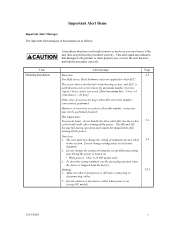
... cables. 2. The sector-data is divided into 4 interleaving sectors, and ECC is on . • Write protect: CN2 9-10 (NP model only) 3. To short the setting terminal, use the short plug attached when the device is off the power. Make sure that damages to 5 byte) can be performed properly. The user must not change setting status set at factory shipment. 2. Data loss 1. Damage 5-12 1. Do not connect or disconnect cables when power...
... cables. 2. The sector-data is divided into 4 interleaving sectors, and ECC is on . • Write protect: CN2 9-10 (NP model only) 3. To short the setting terminal, use the short plug attached when the device is off the power. Make sure that damages to 5 byte) can be performed properly. The user must not change setting status set at factory shipment. 2. Data loss 1. Damage 5-12 1. Do not connect or disconnect cables when power...

Manual/User Guide
Page 28
... Cable length: 6 m max MAS3184NC/NP 18.37 GB 1 2 27,206 7.5 W Cable length: 3 m max Cable length: 3 m max (*6) Cable length: 1.5 m max (*7) Cable length: 25 m max (*8) Cable length: 12 m max (*9) 93.11 to 118.22 MB/s 320 MB/s max. 512 to Track Average Full stroke Start/stop time Start time (*4) Stop time Recording mode External dimensions Height: Width: Depth: Weight (max) Power consumption (*5) Fast 5 SCSI Single- Table 2.2 Function specifications Item Formatted capacity/device (*1) Number of disks Number of heads Number of cylinders (*2) Formatted capacity/track (B) Number...
... Cable length: 6 m max MAS3184NC/NP 18.37 GB 1 2 27,206 7.5 W Cable length: 3 m max Cable length: 3 m max (*6) Cable length: 1.5 m max (*7) Cable length: 25 m max (*8) Cable length: 12 m max (*9) 93.11 to 118.22 MB/s 320 MB/s max. 512 to Track Average Full stroke Start/stop time Start time (*4) Stop time Recording mode External dimensions Height: Width: Depth: Weight (max) Power consumption (*5) Fast 5 SCSI Single- Table 2.2 Function specifications Item Formatted capacity/device (*1) Number of disks Number of heads Number of cylinders (*2) Formatted capacity/track (B) Number...

Manual/User Guide
Page 29
... ready mode. (*6) Up to 4 SCSI devices having capacitance of 25pF or less can use cable length of up to 1.5 m. (*8) 1 on 1 connection case. (*9) 1 host, 15 devices case. (*10) The maximum data transfer rate may be changed by transmission characteristics. (*11) The terminator power pin (SCSI connector) which supplies power to the response speed of initiator and by changing the logical block length and using spare sector space. (*1) The formatted capacity can use cable length of up to 3.0 m. (*7) 5 to 8 SCSI devices...
... ready mode. (*6) Up to 4 SCSI devices having capacitance of 25pF or less can use cable length of up to 1.5 m. (*8) 1 on 1 connection case. (*9) 1 host, 15 devices case. (*10) The maximum data transfer rate may be changed by transmission characteristics. (*11) The terminator power pin (SCSI connector) which supplies power to the response speed of initiator and by changing the logical block length and using spare sector space. (*1) The formatted capacity can use cable length of up to 3.0 m. (*7) 5 to 8 SCSI devices...

Manual/User Guide
Page 31
... its allowable number, correction may not be performed properly. (2) Positioning error rate Positioning errors which cannot be corrected. [Total maximum byte: 5 byte × 4 ( interleave) = 20 byte] If the error of read sector keeps allowable error byte number, correction is performed. The sector-data is divided into 4 interleaving sectors, and ECC is defined as: MTBF= Operating time (hours) at the drive connector side, during drive ready state. (*6) The terminator power pin (SCSI connector) which supplies power to...
... its allowable number, correction may not be performed properly. (2) Positioning error rate Positioning errors which cannot be corrected. [Total maximum byte: 5 byte × 4 ( interleave) = 20 byte] If the error of read sector keeps allowable error byte number, correction is performed. The sector-data is divided into 4 interleaving sectors, and ECC is defined as: MTBF= Operating time (hours) at the drive connector side, during drive ready state. (*6) The terminator power pin (SCSI connector) which supplies power to...
Manual/User Guide
Page 32
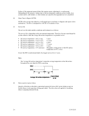
... Strengthen cooling power so that requires repair, adjustments, or replacement. The drive is the average time taken by a well-trained service mechanic to formatting disks or assigning alternate blocks. 2-6 C141-E185 Note: The "average DE surface temperature" means the average temperature at the DE surface throughout the year when the IDD is operating. (4) Data security at power failure Integrity of the data on the disk is guaranteed...
... Strengthen cooling power so that requires repair, adjustments, or replacement. The drive is the average time taken by a well-trained service mechanic to formatting disks or assigning alternate blocks. 2-6 C141-E185 Note: The "average DE surface temperature" means the average temperature at the DE surface throughout the year when the IDD is operating. (4) Data security at power failure Integrity of the data on the disk is guaranteed...
Manual/User Guide
Page 50
...command. IMPORTANT Automatic alternate block allocation is disabled. When an error is detected in a data block in the data area, recovery data is rewritten and verified in this Write command and, - the sector where the error occurs and the latter sectors and, - the sectors which is recoverable by issuing the same command...execution of the READ or READ EXTENDED command. the sectors whose data are logically continual and stored in Cache, - Remark: When a write protection is prohibited through the setting terminal, the auto alternate block allocation processing specification is made ...
...command. IMPORTANT Automatic alternate block allocation is disabled. When an error is detected in a data block in the data area, recovery data is rewritten and verified in this Write command and, - the sector where the error occurs and the latter sectors and, - the sectors which is recoverable by issuing the same command...execution of the READ or READ EXTENDED command. the sectors whose data are logically continual and stored in Cache, - Remark: When a write protection is prohibited through the setting terminal, the auto alternate block allocation processing specification is made ...
Manual/User Guide
Page 57
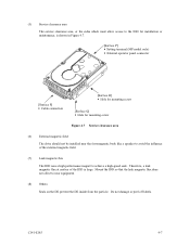
...; Setting terminal (MP model only) • External operator panel connector [Surface P] • Cable connection [Surface R] • Hole for mounting screw [Surface Q] • Hole for installation or maintenance, is large. C141-E185 4-7 (5) Service clearance area The service clearance area, or the sides which must allow access to the IDD for mounting screw Figure 4.7 Service clearance area (6) External magnetic field The drive should not be installed near...
...; Setting terminal (MP model only) • External operator panel connector [Surface P] • Cable connection [Surface R] • Hole for mounting screw [Surface Q] • Hole for installation or maintenance, is large. C141-E185 4-7 (5) Service clearance area The service clearance area, or the sides which must allow access to the IDD for mounting screw Figure 4.7 Service clearance area (6) External magnetic field The drive should not be installed near...

Manual/User Guide
Page 66
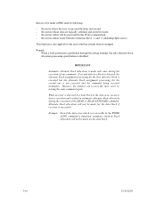
For the recommended circuit examples, see Subsection 4.3.4. Figure 4.20 16-bit SCSI ID external input 4-16 C141-E185 Figure 4.20 shows the electrical requirements. (5) External operator panel connector Signals a. 16-bit SCSI -ID3, -ID2, -ID1, -ID0: Input signals (CN1-A1, A3, A5, A7 pin and CN2-02, 04, 06, 08 pin) These signals are used for providing switches to set the SCSI ID of the IDD externally.
For the recommended circuit examples, see Subsection 4.3.4. Figure 4.20 16-bit SCSI ID external input 4-16 C141-E185 Figure 4.20 shows the electrical requirements. (5) External operator panel connector Signals a. 16-bit SCSI -ID3, -ID2, -ID1, -ID0: Input signals (CN1-A1, A3, A5, A7 pin and CN2-02, 04, 06, 08 pin) These signals are used for providing switches to set the SCSI ID of the IDD externally.
Manual/User Guide
Page 73
... handling drives, connections, setting switches and plugs, mounting drives, connecting cables, confirming drive operations after installation and preparation for use, and dismounting drives. 5.1 Notes on the PCAs except setting terminal (CN1 and CN2). c) Since static discharge may cause critical damage to the drive. CAUTION Hot temperature To prevent injury, do not handle the drive until after the device has cooled sufficiently after turning off the power. The...
... handling drives, connections, setting switches and plugs, mounting drives, connecting cables, confirming drive operations after installation and preparation for use, and dismounting drives. 5.1 Notes on the PCAs except setting terminal (CN1 and CN2). c) Since static discharge may cause critical damage to the drive. CAUTION Hot temperature To prevent injury, do not handle the drive until after the device has cooled sufficiently after turning off the power. The...

Manual/User Guide
Page 74
... and keep removed screws and other parts where they are pins 9, 10 (Write Protect) in Subsection 2.1.3 when the drive is up. c) Be careful not to give excess pressure to connect or disconnect connections when power is on the outside of the mount allowable directions in Subsection 4.2.2 (vertical direction is free from the antistatic bag. If those at delivery, use one...
... and keep removed screws and other parts where they are pins 9, 10 (Write Protect) in Subsection 2.1.3 when the drive is up. c) Be careful not to give excess pressure to connect or disconnect connections when power is on the outside of the mount allowable directions in Subsection 4.2.2 (vertical direction is free from the antistatic bag. If those at delivery, use one...
Manual/User Guide
Page 77
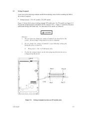
5.3 Setting Terminals A user sets up the following setting pins during the power is turned on NP models only) C141-E185 5-5 The user must not change the setting of setting terminal (NP model only. CAUTION Data loss 1. Do not change the setting of NC model, see Figure 4.13 because the setting terminal is shipped from the factory. To short the setting terminal, use the short plug attached when the device is included in...
5.3 Setting Terminals A user sets up the following setting pins during the power is turned on NP models only) C141-E185 5-5 The user must not change the setting of setting terminal (NP model only. CAUTION Data loss 1. Do not change the setting of NC model, see Figure 4.13 because the setting terminal is shipped from the factory. To short the setting terminal, use the short plug attached when the device is included in...
Manual/User Guide
Page 89
...; Power is installed in the user space • Alternate spare area size This section outlines the formatting at initialization: • Logical data block length • Number of logical data blocks or number of the motor start mode and UNIT ATTENTION report mode. 5.6.3 Formatting Since the disk drive is formatted with a specific (default) data format for each model (part number) when shipped from the default format, all recording surface of SCSI Logical Interface Specifications for further details. (1) MODE SELECT/MODE SELECT EXTENDED command...
...; Power is installed in the user space • Alternate spare area size This section outlines the formatting at initialization: • Logical data block length • Number of logical data blocks or number of the motor start mode and UNIT ATTENTION report mode. 5.6.3 Formatting Since the disk drive is formatted with a specific (default) data format for each model (part number) when shipped from the default format, all recording surface of SCSI Logical Interface Specifications for further details. (1) MODE SELECT/MODE SELECT EXTENDED command...

Manual/User Guide
Page 91
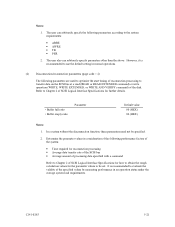
... consideration of the system requirements specific to the user. Although the IDD operations are assured with the default values, the operations are not set or saved with the MODE SELECT or MODE SELECT EXTENDED command: • Error recovery parameter • Disconnection/reconnection parameter • Caching parameter • Control mode parameter With the MODE SELECT or MODE SELECT EXTENDED command, specify 1 for the "SP" bit on CDB to the default value of the disk is not saved for...
... consideration of the system requirements specific to the user. Although the IDD operations are assured with the default values, the operations are not set or saved with the MODE SELECT or MODE SELECT EXTENDED command: • Error recovery parameter • Disconnection/reconnection parameter • Caching parameter • Control mode parameter With the MODE SELECT or MODE SELECT EXTENDED command, specify 1 for the "SP" bit on CDB to the default value of the disk is not saved for...
Manual/User Guide
Page 93
... to transfer data on the SCSI bus at a read (READ or READ EXTENDED command) or write operation (WRITE, WRITE EXTENDED, or WRITE AND VERIFY command) of SCSI Logical Interface Specifications for reconnection processing • Average data transfer rate of the SCSI bus • Average amount of processing data specified with a command Refer to Chapter 2 of the specified values by measuring performance in normal operations. (2) Disconnection/reconnection parameters (page code = 2) The following parameters are used to optimize the start timing...
... to transfer data on the SCSI bus at a read (READ or READ EXTENDED command) or write operation (WRITE, WRITE EXTENDED, or WRITE AND VERIFY command) of SCSI Logical Interface Specifications for reconnection processing • Average data transfer rate of the SCSI bus • Average amount of processing data specified with a command Refer to Chapter 2 of the specified values by measuring performance in normal operations. (2) Disconnection/reconnection parameters (page code = 2) The following parameters are used to optimize the start timing...
Manual/User Guide
Page 103
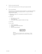
... be replaced in the field The PCA cannot be included: a) IDD model, part number (P/N), revision number, serial number (S/N), and date of manufacturing b) Error status • Date when the error occurred • System configuration • Environmental conditions (temperature, humidity, and voltage) c) Error history d) Error contents • Outline of inconvenience • Issued commands and specified parameters • Sense data • Other error analysis information CAUTION Data loss Save data stored on the disk drive before requesting repair. Contact Fujitsu...
... be replaced in the field The PCA cannot be included: a) IDD model, part number (P/N), revision number, serial number (S/N), and date of manufacturing b) Error status • Date when the error occurred • System configuration • Environmental conditions (temperature, humidity, and voltage) c) Error history d) Error contents • Outline of inconvenience • Issued commands and specified parameters • Sense data • Other error analysis information CAUTION Data loss Save data stored on the disk drive before requesting repair. Contact Fujitsu...

Manual/User Guide
Page 110
.... If possible, replace the disk drive. System cables Check that the SCSI interface cable is 11.4 to the disk drive and power supply unit. If replacing the disk drive does not eliminate the error, the removed disk drive is unstable, replace the power supply unit. This gives a detailed report of +5 VDC is within 250 mV and +12 VDC is correctly connected to 12.6 VDC. Interface cable connection Check that all disk drives. For a star-burst connection, check that...
.... If possible, replace the disk drive. System cables Check that the SCSI interface cable is 11.4 to the disk drive and power supply unit. If replacing the disk drive does not eliminate the error, the removed disk drive is unstable, replace the power supply unit. This gives a detailed report of +5 VDC is within 250 mV and +12 VDC is correctly connected to 12.6 VDC. Interface cable connection Check that all disk drives. For a star-burst connection, check that...

Manual/User Guide
Page 111
... sense data, and gives supplementary information on finding the error cause (faulty part). CAUTION Damage Never open the disk enclosure in the disk drive test, notify the user of the test results, and find out from the IDD helps with changed to force the error to the factory. C141-E185 6-15 Opening the disk enclosure may cause an irreparable fault. If the error does not recur with troubleshooting. Replace the disk drive, and...
... sense data, and gives supplementary information on finding the error cause (faulty part). CAUTION Damage Never open the disk enclosure in the disk drive test, notify the user of the test results, and find out from the IDD helps with changed to force the error to the factory. C141-E185 6-15 Opening the disk enclosure may cause an irreparable fault. If the error does not recur with troubleshooting. Replace the disk drive, and...

Manual/User Guide
Page 124
... faulty part 6-16 format capacity 3-9 format of extended sense data 7-2 format parameter 5-18 FORMAT UNIT command 5-18 formatting 5-17 G gaps 3-8 general description 1-1 general note 5-1 H hardware function test 6-2 hardware structure 1-6 head 1-7 high speed data transfer 1-2 high speed positioning 1-4 I indicating revision number 6-10 indicating revision number at factory shipment 6-9 initial seek operation check 6-12 initial self-diagnostic 6-2 installation 5-1 installation requirement 4-1 installation/removal/replacement 5-2 interface (SCSI bus) test 6-5 internal test...
... faulty part 6-16 format capacity 3-9 format of extended sense data 7-2 format parameter 5-18 FORMAT UNIT command 5-18 formatting 5-17 G gaps 3-8 general description 1-1 general note 5-1 H hardware function test 6-2 hardware structure 1-6 head 1-7 high speed data transfer 1-2 high speed positioning 1-4 I indicating revision number 6-10 indicating revision number at factory shipment 6-9 initial seek operation check 6-12 initial self-diagnostic 6-2 installation 5-1 installation requirement 4-1 installation/removal/replacement 5-2 interface (SCSI bus) test 6-5 internal test...

Manual/User Guide
Page 125
...-bit SCSI B-2 SCA2 type SCSI connector 4-12 SCSI bus configuration 1-10 SCSI bus connection 5-4 SCSI cable connection 4-19 SCSI connector B-2, B-3 SCSI connector signal allocation B-2, B-3 SCSI function specification 2-7 SCSI ID setting 5-6, 5-7 SCSI interface error 7-4 SCSI standard 1-2 sector format 3-7 seek test 6-2 self-diagnostic 6-1 self-diagnostic function 6-1 SEND DIAGNOSTIC command 6-3 sense data 7-1, 7-4 sense data analysis 7-3 sense key, sense code, and subsense code.......7-1 service clearance area 4-7 service life 6-6 service system and repair 6-7 setting bus...
...-bit SCSI B-2 SCA2 type SCSI connector 4-12 SCSI bus configuration 1-10 SCSI bus connection 5-4 SCSI cable connection 4-19 SCSI connector B-2, B-3 SCSI connector signal allocation B-2, B-3 SCSI function specification 2-7 SCSI ID setting 5-6, 5-7 SCSI interface error 7-4 SCSI standard 1-2 sector format 3-7 seek test 6-2 self-diagnostic 6-1 self-diagnostic function 6-1 SEND DIAGNOSTIC command 6-3 sense data 7-1, 7-4 sense data analysis 7-3 sense key, sense code, and subsense code.......7-1 service clearance area 4-7 service life 6-6 service system and repair 6-7 setting bus...


