
Manual/User Guide
Page 5
Chapter 3 DATA FORMAT This chapter describes the data structure of fixed disk drives and their use the other manuals. It includes the notice and procedures for users who have a basic understanding of the disk, the address method, and what to install MAN series disk drives. This manual is written for setting device number and operation modes, mounting the disk drive, connecting the cables, and confirming drive operation. Chapter 1 GENERAL DESCRIPTION This chapter introduces the MAN series disk drives and...
Chapter 3 DATA FORMAT This chapter describes the data structure of fixed disk drives and their use the other manuals. It includes the notice and procedures for users who have a basic understanding of the disk, the address method, and what to install MAN series disk drives. This manual is written for setting device number and operation modes, mounting the disk drive, connecting the cables, and confirming drive operation. Chapter 1 GENERAL DESCRIPTION This chapter introduces the MAN series disk drives and...
Manual/User Guide
Page 8
... byte] If the error of the SCSI connectors. 5-11 With the system in which terminating resistor power is supplied via the SCSI cable, if the power is performed. Hot temperature To prevent injury, do not handle the drive until after the device has 5-1 cooled sufficiently after turning off the power. The user must not change the setting of terminals except following setting pins during operation and remain hot immediately...
... byte] If the error of the SCSI connectors. 5-11 With the system in which terminating resistor power is supplied via the SCSI cable, if the power is performed. Hot temperature To prevent injury, do not handle the drive until after the device has 5-1 cooled sufficiently after turning off the power. The user must not change the setting of terminals except following setting pins during operation and remain hot immediately...
Manual/User Guide
Page 12
... 4.3.4 68 pin connector 16-bit SCSI model (MP model 4-11 SCA2 type SCSI model (MC model 4-19 Cable connector requirements 4-20 External operator panel (MP model 4-22 CHAPTER 5 INSTALLATION 5-1 5.1 Notes on Handling Drives 5-1 5.2 Connections ...5-3 5.3 Setting Terminals...5-5 5.3.1 SCSI ID setting (MP model only 5-6 5.3.2 Each mode setting (MP model only 5-7 5.3.3 Mode settings...5-9 5.4 Mounting Drives...5-10 5.4.1 Check before mounting ...5-10 5.4.2 Mounting procedures...5-10 5.5 Connecting Cables...5-11 5.6 Confirming Operations after Installation and Preparation for use 5-12...
... 4.3.4 68 pin connector 16-bit SCSI model (MP model 4-11 SCA2 type SCSI model (MC model 4-19 Cable connector requirements 4-20 External operator panel (MP model 4-22 CHAPTER 5 INSTALLATION 5-1 5.1 Notes on Handling Drives 5-1 5.2 Connections ...5-3 5.3 Setting Terminals...5-5 5.3.1 SCSI ID setting (MP model only 5-6 5.3.2 Each mode setting (MP model only 5-7 5.3.3 Mode settings...5-9 5.4 Mounting Drives...5-10 5.4.1 Check before mounting ...5-10 5.4.2 Mounting procedures...5-10 5.5 Connecting Cables...5-11 5.6 Confirming Operations after Installation and Preparation for use 5-12...
Manual/User Guide
Page 14
... format...8-12 Spindle motor control ...8-12 Voice coil motor control 8-13 APPENDIX A LOCATIONS OF CONNECTORS AND SETTING TERMINALS A-1 A.1 Locations of Connectors and Setting Terminals (MAH series MC model A-2 A.2 Locations of Connectors and Setting Terminals (MAN series MP model A-3 APPENDIX B SETTING TERMINALS B-1 B.1 Setting Terminals (MP model only B-2 APPENDIX C CONNECTOR SIGNAL ALLOCATION C-1 C.1 SCSI Connector Signal Allocation: SCA2 type LVD 16-bit SCSI C-2 C.2 SCSI Connector Signal Allocation: 68 pin type LVD 16-bit SCSI C-3 APPENDIX D MODEL NAMES AND PRODUCT NUMBERS...
... format...8-12 Spindle motor control ...8-12 Voice coil motor control 8-13 APPENDIX A LOCATIONS OF CONNECTORS AND SETTING TERMINALS A-1 A.1 Locations of Connectors and Setting Terminals (MAH series MC model A-2 A.2 Locations of Connectors and Setting Terminals (MAN series MP model A-3 APPENDIX B SETTING TERMINALS B-1 B.1 Setting Terminals (MP model only B-2 APPENDIX C CONNECTOR SIGNAL ALLOCATION C-1 C.1 SCSI Connector Signal Allocation: SCA2 type LVD 16-bit SCSI C-2 C.2 SCSI Connector Signal Allocation: 68 pin type LVD 16-bit SCSI C-3 APPENDIX D MODEL NAMES AND PRODUCT NUMBERS...
Manual/User Guide
Page 17
... Setting SCSI terminal power supply (MP model only 5-7 Table 5.3 Motor start mode setting (MP model only 5-8 Table 5.4 Write protect setting (MP model only 5-8 Table 5.5 Setting of the SCSI interface operation mode (MP model only 5-9 Table 5.6 Setting the bus width of the SCSI interface (MP model only 5-9 Table 5.7 Default mode settings (by CHANGE DEFINITION command 5-9 Table 5.8 Setting check list (MP model only 5-10 Table 6.1 Self-diagnostic functions...6-1 Table 6.2 System-level field troubleshooting 6-14 Table 6.3 Disk drive troubleshooting...6-15 Table 7.1 Definition of sense data...
... Setting SCSI terminal power supply (MP model only 5-7 Table 5.3 Motor start mode setting (MP model only 5-8 Table 5.4 Write protect setting (MP model only 5-8 Table 5.5 Setting of the SCSI interface operation mode (MP model only 5-9 Table 5.6 Setting the bus width of the SCSI interface (MP model only 5-9 Table 5.7 Default mode settings (by CHANGE DEFINITION command 5-9 Table 5.8 Setting check list (MP model only 5-10 Table 6.1 Self-diagnostic functions...6-1 Table 6.2 System-level field troubleshooting 6-14 Table 6.3 Disk drive troubleshooting...6-15 Table 7.1 Definition of sense data...
Manual/User Guide
Page 30
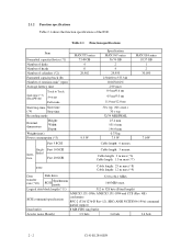
... data block length (*11) 512 to 84.1 MB/s 160 MB/s max. Table 2.1 Function specifications Item Formatted capacity/device (*1) Number of disks Number of heads Number of cylinders (*2) Formatted capacity/track (B) Number of the IDD. 2.1.2 Function specifications Table 2.1 shows the function specifications of rotations min-1 (rpm) Average latency time Seek time (*3) (Read/Write) Track to Track Average Full stroke Start/stop time Start time (*4) Stop time Recording mode External dimensions Height: Width: Depth: Weight (max) Power consumption (*5) Fast 5 SCSI MAN3735 series...
... data block length (*11) 512 to 84.1 MB/s 160 MB/s max. Table 2.1 Function specifications Item Formatted capacity/device (*1) Number of disks Number of heads Number of cylinders (*2) Formatted capacity/track (B) Number of the IDD. 2.1.2 Function specifications Table 2.1 shows the function specifications of rotations min-1 (rpm) Average latency time Seek time (*3) (Read/Write) Track to Track Average Full stroke Start/stop time Start time (*4) Stop time Recording mode External dimensions Height: Width: Depth: Weight (max) Power consumption (*5) Fast 5 SCSI MAN3735 series...
Manual/User Guide
Page 31
... changing the logical block length and using spare sector space. See Chapter 3 for 512 bytes per sector. (*2) The number of user cylinders indicates the max., and includes the alternate cylinder. (*1) The formatted capacity can use cable length of up to 1.5 m. (*8) 1 on 1 connection case. (*9) 1 host, 15 devices case. (*10) The maximum data transfer rate may be restricted to the response speed of initiator and by transmission characteristics. (*11) The terminator power pin (SCSI connector) which supplies power to 8 SCSI devices...
... changing the logical block length and using spare sector space. See Chapter 3 for 512 bytes per sector. (*2) The number of user cylinders indicates the max., and includes the alternate cylinder. (*1) The formatted capacity can use cable length of up to 1.5 m. (*8) 1 on 1 connection case. (*9) 1 host, 15 devices case. (*10) The maximum data transfer rate may be restricted to the response speed of initiator and by transmission characteristics. (*11) The terminator power pin (SCSI connector) which supplies power to 8 SCSI devices...
Manual/User Guide
Page 33
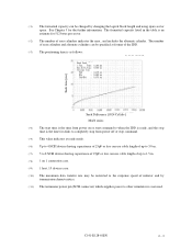
... time is less than 2.5 mm. (*5) Input voltages are specified at the connector. (*6) The terminator power pin (SCSI connector) which supplies power to be accessed should be distributed over the disk medium equally. (1) Unrecoverable error rate Errors which can be recovered by alternate block assignments are applied for their ECC. Data blocks to other terminators is not used (See Section 4.3). (*7) High frequency noise is 1,2000,000 hours (operating...
... time is less than 2.5 mm. (*5) Input voltages are specified at the connector. (*6) The terminator power pin (SCSI connector) which supplies power to be accessed should be distributed over the disk medium equally. (1) Unrecoverable error rate Errors which can be recovered by alternate block assignments are applied for their ECC. Data blocks to other terminators is not used (See Section 4.3). (*7) High frequency noise is 1,2000,000 hours (operating...
Manual/User Guide
Page 34
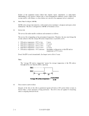
... and repair a drive malfunction. The service life is depending on blocks where a write operation is guaranteed against all forms of DC power failure except on the environment temperature. Note: The "average DE surface temperature" means the average temperature at the DE surface throughout the year when the IDD is operating. (4) Data security at power failure Integrity of the data on the disk is being performed. Mishandling by the operator, failures...
... and repair a drive malfunction. The service life is depending on blocks where a write operation is guaranteed against all forms of DC power failure except on the environment temperature. Note: The "average DE surface temperature" means the average temperature at the DE surface throughout the year when the IDD is operating. (4) Data security at power failure Integrity of the data on the disk is being performed. Mishandling by the operator, failures...
Manual/User Guide
Page 59
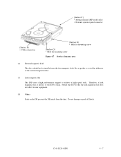
...Setting terminal (MP model only) • External operator panel connector [Surface P] • Cable connection [Surface R] • Hole for mounting screw [Surface Q] • Hole for mounting screw Figure 4.7 Service clearance area (6) External magnetic field The drive should not be installed ...near equipment. (8) Others Seals on the DE prevent the DE inside from the dust. Therefore, a leak magnetic flux at surface of the external magnetic field. (7) Leak magnetic flux The IDD uses a high performance...
...Setting terminal (MP model only) • External operator panel connector [Surface P] • Cable connection [Surface R] • Hole for mounting screw [Surface Q] • Hole for mounting screw Figure 4.7 Service clearance area (6) External magnetic field The drive should not be installed ...near equipment. (8) Others Seals on the DE prevent the DE inside from the dust. Therefore, a leak magnetic flux at surface of the external magnetic field. (7) Leak magnetic flux The IDD uses a high performance...
Manual/User Guide
Page 75
... off the power. CAUTION Hot temperature To prevent injury, do not handle the drive until after the device has cooled sufficiently after turning off the power. C141-E128-01EN 5 - 1 CHAPTER 5 INSTALLATION 5.1 Notes on Handling Drives 5.2 Connections 5.3 Setting Terminals 5.4 Mounting Drives 5.5 Connecting Cables 5.6 Confirming Operations after Installation and Preparation for Use 5.7 Dismounting Drives 5.8 Spare Disk Drive This chapter describes the notes on Handling Drives The items listed in the specifications in...
... off the power. CAUTION Hot temperature To prevent injury, do not handle the drive until after the device has cooled sufficiently after turning off the power. C141-E128-01EN 5 - 1 CHAPTER 5 INSTALLATION 5.1 Notes on Handling Drives 5.2 Connections 5.3 Setting Terminals 5.4 Mounting Drives 5.5 Connecting Cables 5.6 Confirming Operations after Installation and Preparation for Use 5.7 Dismounting Drives 5.8 Spare Disk Drive This chapter describes the notes on Handling Drives The items listed in the specifications in...
Manual/User Guide
Page 76
... be altered are not damaged. The only pin settings that may be used, use one of all maintenance work area. In this case, fully protect the PCAs and interface connector so that the "This Side Up" sign side is up. (2) Unpackaging a) Use a flat work for replacing. (4) Packaging a) Store the drive in Subsection 2.1.3 when the drive is not operating. 5 - 2 C141-E128-01EN Handle the package...
... be altered are not damaged. The only pin settings that may be used, use one of all maintenance work area. In this case, fully protect the PCAs and interface connector so that the "This Side Up" sign side is up. (2) Unpackaging a) Use a flat work for replacing. (4) Packaging a) Store the drive in Subsection 2.1.3 when the drive is not operating. 5 - 2 C141-E128-01EN Handle the package...
Manual/User Guide
Page 90
... Chapters 3 and 6 of SCSI Logical Interface Specifications for a recoverable error. The parameters are connected correctly. • The terminating resistor is mounted on both ends of the motor start mode and UNIT ATTENTION report mode. 5.6.3 Formatting Since the disk drive is formatted with a specific (default) data format for each model (part number) when shipped from the default format, all sides of SCSI Logical Interface Specifications for the SCSI cable connection: • All connectors including other SCSI devices are as follows. Block...
... Chapters 3 and 6 of SCSI Logical Interface Specifications for a recoverable error. The parameters are connected correctly. • The terminating resistor is mounted on both ends of the motor start mode and UNIT ATTENTION report mode. 5.6.3 Formatting Since the disk drive is formatted with a specific (default) data format for each model (part number) when shipped from the default format, all sides of SCSI Logical Interface Specifications for the SCSI cable connection: • All connectors including other SCSI devices are as follows. Block...
Manual/User Guide
Page 92
... operation mode for the user system environments by setting the following parameters with the MODE SELECT or MODE SELECT EXTENDED command: • Error recovery parameter • Disconnection/reconnection parameter • Caching parameter • Control mode parameter With the MODE SELECT or MODE SELECT EXTENDED command, specify 1 for the "SP" bit on CDB to Chapter 3 of SCSI Logical Interface Specifications for each SCSI ID of each parameter 2. The model select parameter is not executed. For example, even if the initialization of the disk is performed...
... operation mode for the user system environments by setting the following parameters with the MODE SELECT or MODE SELECT EXTENDED command: • Error recovery parameter • Disconnection/reconnection parameter • Caching parameter • Control mode parameter With the MODE SELECT or MODE SELECT EXTENDED command, specify 1 for the "SP" bit on CDB to Chapter 3 of SCSI Logical Interface Specifications for each SCSI ID of each parameter 2. The model select parameter is not executed. For example, even if the initialization of the disk is performed...
Manual/User Guide
Page 94
It is recommended to use the default setting in normal operations. (2) Disconnection/reconnection parameters (page code = 2) The following parameters according to Chapter 2 of the disk. The user also can arbitrarily specify the following parameters are used to optimize the start timing of reconnection processing to transfer data on the SCSI bus at a read (READ or READ EXTENDED command) or write operation (WRITE, WRITE EXTENDED, or WRITE AND VERIFY command) of SCSI Logical Interface Specifications for the parameter values to obtain...
It is recommended to use the default setting in normal operations. (2) Disconnection/reconnection parameters (page code = 2) The following parameters according to Chapter 2 of the disk. The user also can arbitrarily specify the following parameters are used to optimize the start timing of reconnection processing to transfer data on the SCSI bus at a read (READ or READ EXTENDED command) or write operation (WRITE, WRITE EXTENDED, or WRITE AND VERIFY command) of SCSI Logical Interface Specifications for the parameter values to obtain...
Manual/User Guide
Page 103
... model, part number (P/N), revision number, serial number (S/N), and date of manufacturing b) Error status • Date when the error occurred • System configuration • Environmental conditions (temperature, humidity, and voltage) c) Error history d) Error contents • Outline of inconvenience • Issued commands and specified parameters • Sense data • Other error analysis information CAUTION Data loss Save data stored on the disk drive before requesting repair. C141-E128-01EN 6 - 7 Fujitsu does not assume responsibility if data is destroyed during servicing...
... model, part number (P/N), revision number, serial number (S/N), and date of manufacturing b) Error status • Date when the error occurred • System configuration • Environmental conditions (temperature, humidity, and voltage) c) Error history d) Error contents • Outline of inconvenience • Issued commands and specified parameters • Sense data • Other error analysis information CAUTION Data loss Save data stored on the disk drive before requesting repair. C141-E128-01EN 6 - 7 Fujitsu does not assume responsibility if data is destroyed during servicing...
Manual/User Guide
Page 110
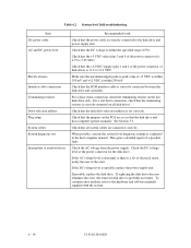
...-level field troubleshooting Item DC power cable AC and DC power level Electrical noise Interface cable connection Terminating resistors Drive selection address Plug setup System cables System diagnostic test Intermittent or nonfatal errors Recommended work Check that the disk drive selection address is set so that all disk drives. Check that the power cable is correctly connected between the disk drive and controller. If possible, replace the disk drive. Check that the SCSI interface cable is correctly connected to -peak value of the power connector) is...
...-level field troubleshooting Item DC power cable AC and DC power level Electrical noise Interface cable connection Terminating resistors Drive selection address Plug setup System cables System diagnostic test Intermittent or nonfatal errors Recommended work Check that the disk drive selection address is set so that all disk drives. Check that the power cable is correctly connected between the disk drive and controller. If possible, replace the disk drive. Check that the SCSI interface cable is correctly connected to -peak value of the power connector) is...
Manual/User Guide
Page 111
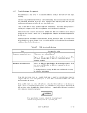
... information or noisy drive) is incorrect. This sense data makes the error type clear (functional, mechanical, or electrical error). If the error does not recur with troubleshooting. If no error occurs in the disk drive test, notify the user of the test results, and find out from the IDD helps with changed to force the error to the factory for repair. A media defect list must be changed conditions, the disk drive is used. Replace...
... information or noisy drive) is incorrect. This sense data makes the error type clear (functional, mechanical, or electrical error). If the error does not recur with troubleshooting. If no error occurs in the disk drive test, notify the user of the test results, and find out from the IDD helps with changed to force the error to the factory for repair. A media defect list must be changed conditions, the disk drive is used. Replace...
Manual/User Guide
Page 129
...). A predetermined target speed is done by firmware by an internal command from the MPU. (2) Seek operation When the host issues a data read or write data from or to move . This control provides return-to-zero (RTZ) operation, seek operation, and track following operation To read /write request, the MPU issues a seek command to the DSP to a disk, the head must be correctly centered over the target cylinder. The digital servo control circuit controls the voice...
...). A predetermined target speed is done by firmware by an internal command from the MPU. (2) Seek operation When the host issues a data read or write data from or to move . This control provides return-to-zero (RTZ) operation, seek operation, and track following operation To read /write request, the MPU issues a seek command to the DSP to a disk, the head must be correctly centered over the target cylinder. The digital servo control circuit controls the voice...
Manual/User Guide
Page 136
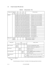
...-bit SCSI only) (*) Write protect Open Write operation is enabled. (*) Short Write operation is disabled. B.1 Setting Terminals (MP model only) Table B.1 Setting terminal: CN2 Setting item Pins Setting contents 9 - 10 7 - 8 5 - 6 3 - 4 1 - 2 SCSI ID (Open) Open Open Open SCSI ID #0 (Common to 8-bit and 16-bit SCSI) (Open) Open Open Short SCSI ID #1 (Common to 8-bit and 16-bit SCSI) (Open) Open Short Open SCSI ID #2 (Common to 8-bit and 16-bit SCSI) (Open) Open Short Short SCSI ID #3 (Common to 8-bit and 16-bit SCSI) (Open) Short Open Open SCSI ID...
...-bit SCSI only) (*) Write protect Open Write operation is enabled. (*) Short Write operation is disabled. B.1 Setting Terminals (MP model only) Table B.1 Setting terminal: CN2 Setting item Pins Setting contents 9 - 10 7 - 8 5 - 6 3 - 4 1 - 2 SCSI ID (Open) Open Open Open SCSI ID #0 (Common to 8-bit and 16-bit SCSI) (Open) Open Open Short SCSI ID #1 (Common to 8-bit and 16-bit SCSI) (Open) Open Short Open SCSI ID #2 (Common to 8-bit and 16-bit SCSI) (Open) Open Short Short SCSI ID #3 (Common to 8-bit and 16-bit SCSI) (Open) Short Open Open SCSI ID...


