
Cleaning & Maintenance
Page 2
... one or more of the FCC Rules. FCC warning: Changes or modifications not expressly approved by the party responsible for a Class B digital device, pursuant to Part 15 of the following measures: • Reorient or relocate the receiving antenna. • Increase the separation between the equipment and receiver. • Connect the equipment...
... one or more of the FCC Rules. FCC warning: Changes or modifications not expressly approved by the party responsible for a Class B digital device, pursuant to Part 15 of the following measures: • Reorient or relocate the receiving antenna. • Increase the separation between the equipment and receiver. • Connect the equipment...
Cleaning & Maintenance
Page 3
...Cet appareil numérique de la classe B est conforme à la norme NMB-003 du Canada. As an ENERGYSTAR ® Partner, Fujitsu Limited declares that this manual may be revised without prior notice. Changes The contents of this scanner meets the ENERGYSTAR ® guidelines for energy... efficiency. No part of this manual may be reproduced in Japan. NOTE • The use of a non-shielded interface cable with Canadian ICES-003. ENERGYSTAR ...
...Cet appareil numérique de la classe B est conforme à la norme NMB-003 du Canada. As an ENERGYSTAR ® Partner, Fujitsu Limited declares that this manual may be revised without prior notice. Changes The contents of this scanner meets the ENERGYSTAR ® guidelines for energy... efficiency. No part of this manual may be reproduced in Japan. NOTE • The use of a non-shielded interface cable with Canadian ICES-003. ENERGYSTAR ...

Cleaning & Maintenance
Page 7
Conventions Important information that requires special attention is indicated as in the part name "Pick roller". vi Official Fujitsu part names are indicated with an initial capital letter, as follows: WARNING WARNING indicates that damage to help you do not follow a procedure correctly. NOTE A NOTE provides "how-to" tips or suggestions to the scanner may result if you perform a procedure correctly. CAUTION CAUTION indicates that personal injury like pinching of fingers or hands may result if you do not follow a procedure correctly.
Conventions Important information that requires special attention is indicated as in the part name "Pick roller". vi Official Fujitsu part names are indicated with an initial capital letter, as follows: WARNING WARNING indicates that damage to help you do not follow a procedure correctly. NOTE A NOTE provides "how-to" tips or suggestions to the scanner may result if you perform a procedure correctly. CAUTION CAUTION indicates that personal injury like pinching of fingers or hands may result if you do not follow a procedure correctly.
Cleaning & Maintenance
Page 8
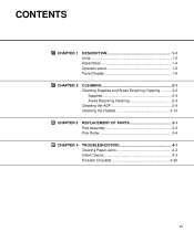
CONTENTS CHAPTER 1 DESCRIPTION 1-1 Units 1-2 Assemblies 1-4 Operator panel 1-5 Panel Display 1-6 CHAPTER 2 CLEANING 2-1 Cleaning Supplies and Areas Requiring Cleaning .......... 2-2 Supplies 2-2 Areas Requiring Cleaning 2-3 Cleaning the ADF 2-4 Cleaning the Flatbed 2-10 CHAPTER 3 REPLACEMENT OF PARTS 3-1 Pad Assembly 3-2 Pick Roller 3-4 CHAPTER 4 TROUBLESHOOTING 4-1 Clearing Paper Jams 4-2 Initial Checks 4-3 Problem Checklist 4-20 vii
CONTENTS CHAPTER 1 DESCRIPTION 1-1 Units 1-2 Assemblies 1-4 Operator panel 1-5 Panel Display 1-6 CHAPTER 2 CLEANING 2-1 Cleaning Supplies and Areas Requiring Cleaning .......... 2-2 Supplies 2-2 Areas Requiring Cleaning 2-3 Cleaning the ADF 2-4 Cleaning the Flatbed 2-10 CHAPTER 3 REPLACEMENT OF PARTS 3-1 Pad Assembly 3-2 Pick Roller 3-4 CHAPTER 4 TROUBLESHOOTING 4-1 Clearing Paper Jams 4-2 Initial Checks 4-3 Problem Checklist 4-20 vii

Cleaning & Maintenance
Page 9
CHAPTER 1 CHAPTER 2 CHAPTER 3 CHAPTER 4 DESCRIPTION CLEANING REPLACEMENT OF PARTS TROUBLESHOOTING TROUBLESHOOTING REPLACEMENT OF PARTS CLEANING D DEESSCCRRIIPTPITOINON
CHAPTER 1 CHAPTER 2 CHAPTER 3 CHAPTER 4 DESCRIPTION CLEANING REPLACEMENT OF PARTS TROUBLESHOOTING TROUBLESHOOTING REPLACEMENT OF PARTS CLEANING D DEESSCCRRIIPTPITOINON
Cleaning & Maintenance
Page 15
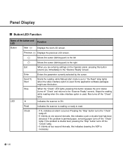
... . Check • If lit, indicates an alarm occurred. Previous Displays the previous LCD screen. Moves the cursor (blinking part) to the left Moves the cursor (blinking part) to the right Exit When you are entering settings on the Operator panel, pressing this indicates a jam or double feed... you immediately to read. Enter Enters the parameter currently selected by the cursor. Some application software packages might use this indicates cleaning the ADF is ON. Read Indicates the scanner is reading or ready to the "Scanner Ready" screen. while Manual start mode is set or ...
... . Check • If lit, indicates an alarm occurred. Previous Displays the previous LCD screen. Moves the cursor (blinking part) to the left Moves the cursor (blinking part) to the right Exit When you are entering settings on the Operator panel, pressing this indicates a jam or double feed... you immediately to read. Enter Enters the parameter currently selected by the cursor. Some application software packages might use this indicates cleaning the ADF is ON. Read Indicates the scanner is reading or ready to the "Scanner Ready" screen. while Manual start mode is set or ...

Cleaning & Maintenance
Page 16
... is provided with a counter display. When the button is pressed This counter increments each time a document is detected. How to check the cleaning cycle or parts replacement cycle. Abrasion counter Abrasion counter counts the accumulated number of sheets that have been scanned in Chapter 6. Paper counter Abrasion counter Counter Function Paper...
... is provided with a counter display. When the button is pressed This counter increments each time a document is detected. How to check the cleaning cycle or parts replacement cycle. Abrasion counter Abrasion counter counts the accumulated number of sheets that have been scanned in Chapter 6. Paper counter Abrasion counter Counter Function Paper...

Cleaning & Maintenance
Page 23
CLEANING Areas Requiring Cleaning Area Name Flatbed ADF Document holding pad Document bed Pad Glass/Sheet guide Pick roller Plastic rollers Feed rollers Pick Arm Rollers Cleaning paper with Cleaner F1 Dry cloth Cotton swab with Cleaner F1 with Cleaner F1 or F2 ADF Plastic rollers Document holding pad Document bed Feed rollers Sheet guide (white part) Pad Plastic rollers Pick roller Glass 2-3
CLEANING Areas Requiring Cleaning Area Name Flatbed ADF Document holding pad Document bed Pad Glass/Sheet guide Pick roller Plastic rollers Feed rollers Pick Arm Rollers Cleaning paper with Cleaner F1 Dry cloth Cotton swab with Cleaner F1 with Cleaner F1 or F2 ADF Plastic rollers Document holding pad Document bed Feed rollers Sheet guide (white part) Pad Plastic rollers Pick roller Glass 2-3

Cleaning & Maintenance
Page 27
Sheet guide (white part) NOTE If the Sheet guide is dirty, the front image may show vertical stripes. 3 Close the ADF to lock the ADF lever. 2-7 CLEANING Sheet guide (white part): Wipe the sheet guide.
Sheet guide (white part) NOTE If the Sheet guide is dirty, the front image may show vertical stripes. 3 Close the ADF to lock the ADF lever. 2-7 CLEANING Sheet guide (white part): Wipe the sheet guide.

Cleaning & Maintenance
Page 31
CHAPTER 3 REPLACEMENT OF PARTS This chapter describes how to replace the pad assembly and the pick roller. Pad Assembly Pick Roller 3-1
CHAPTER 3 REPLACEMENT OF PARTS This chapter describes how to replace the pad assembly and the pick roller. Pad Assembly Pick Roller 3-1

Cleaning & Maintenance
Page 33
REPLACEMENT OF PARTS 3 Slide the Pad Assembly to the left photo. CAUTION Don't hold the sensor arm with the Pad assembly. Pad assembly 4 Attach the Pad Assembly to the ADF in the reverse sequence of the Pad assembly as shown in the left and pull it stops. 5 Close the ADF. 3-3 Then, being careful not to the right until it towards you. NOTE Fit the Pad assembly pin into the larger hole, then slide it to hook the Pad spring, remove the Pad Assembly. NOTE Hold both ends of step 3.
REPLACEMENT OF PARTS 3 Slide the Pad Assembly to the left photo. CAUTION Don't hold the sensor arm with the Pad assembly. Pad assembly 4 Attach the Pad Assembly to the ADF in the reverse sequence of the Pad assembly as shown in the left and pull it stops. 5 Close the ADF. 3-3 Then, being careful not to the right until it towards you. NOTE Fit the Pad assembly pin into the larger hole, then slide it to hook the Pad spring, remove the Pad Assembly. NOTE Hold both ends of step 3.

Cleaning & Maintenance
Page 35
Stopper Pick roller 2 Pick roller 1 REPLACEMENT OF PARTS Position for Replacement 3-5 Then lift the right side of the cover and remove it. 4 To remove the Pick rollers, turn the stopper counterclockwise. 3 With both hands, lift up Guide A and disengage its tip from the right hole.
Stopper Pick roller 2 Pick roller 1 REPLACEMENT OF PARTS Position for Replacement 3-5 Then lift the right side of the cover and remove it. 4 To remove the Pick rollers, turn the stopper counterclockwise. 3 With both hands, lift up Guide A and disengage its tip from the right hole.

Cleaning & Maintenance
Page 37
Then, slide Pick roller 1 toward the right side. NOTE Make sure that the shaft is securely fixed to the bearings. 3-7 NOTE Pick roller 1 has a groove in its rubber. REPLACEMENT OF PARTS 7 To attach the new Pick rollers, place Pick roller 1 from the right side above the bearing for Pick roller 1. Put the shaft of Pick roller 1 into the bearing.
Then, slide Pick roller 1 toward the right side. NOTE Make sure that the shaft is securely fixed to the bearings. 3-7 NOTE Pick roller 1 has a groove in its rubber. REPLACEMENT OF PARTS 7 To attach the new Pick rollers, place Pick roller 1 from the right side above the bearing for Pick roller 1. Put the shaft of Pick roller 1 into the bearing.

Cleaning & Maintenance
Page 39
9 Turn the stopper clockwise to secure the Pick rollers. Stopper REPLACEMENT OF PARTS Operating Position 3-9
9 Turn the stopper clockwise to secure the Pick rollers. Stopper REPLACEMENT OF PARTS Operating Position 3-9

Cleaning & Maintenance
Page 47
4 Symptom Pictures and photographs are not read correctly. TROUBLESHOOTING 4-7 YES Is halftone or dither processing selected? NO Select the halftone or dithering mode from the host computer. Clean the dirty parts. (See p. 2-5, p. 2-7, p. 2-10) YES Contact the manufacturer's authorized service center. NO Select the "Photo" mode (White level following "Off") through the scanner setting menu in the software. Is the "Photo" mode selected? YES Are the Document bed, NO Document holding pad, glass, and sheet guides clean?
4 Symptom Pictures and photographs are not read correctly. TROUBLESHOOTING 4-7 YES Is halftone or dither processing selected? NO Select the halftone or dithering mode from the host computer. Clean the dirty parts. (See p. 2-5, p. 2-7, p. 2-10) YES Contact the manufacturer's authorized service center. NO Select the "Photo" mode (White level following "Off") through the scanner setting menu in the software. Is the "Photo" mode selected? YES Are the Document bed, NO Document holding pad, glass, and sheet guides clean?

Cleaning & Maintenance
Page 48
NO Select the "Line Art" mode from the host computer. NO Are the Document bed, NO Document holding pad, glass, and sheet guides clean? Clean the dirty parts. (See p. 2-5, p. 2-7, p. 2-10) YES Contact the manufacturer's authorized service center. 4-8 via software. YES 3mm YES Is there any printed text on Select the "Photo" mode the first 3mm of the (White level following "Off") document? Is the "Line Art" mode selected? 5 Symptom Characters and lines are not read correctly.
NO Select the "Line Art" mode from the host computer. NO Are the Document bed, NO Document holding pad, glass, and sheet guides clean? Clean the dirty parts. (See p. 2-5, p. 2-7, p. 2-10) YES Contact the manufacturer's authorized service center. 4-8 via software. YES 3mm YES Is there any printed text on Select the "Photo" mode the first 3mm of the (White level following "Off") document? Is the "Line Art" mode selected? 5 Symptom Characters and lines are not read correctly.

Cleaning & Maintenance
Page 49
... pressed or is there anything heavy on a flat, even surface or attach the rubber feet. Clean the dirty parts. (See p. 2-5, p. 2-7, p. 2-10) YES During rear read operation with the ADF, is the top of the ADF or put anything heavy on an even NO and flat surface or are distorted or unclear. Are the...
... pressed or is there anything heavy on a flat, even surface or attach the rubber feet. Clean the dirty parts. (See p. 2-5, p. 2-7, p. 2-10) YES During rear read operation with the ADF, is the top of the ADF or put anything heavy on an even NO and flat surface or are distorted or unclear. Are the...
Cleaning & Maintenance
Page 60
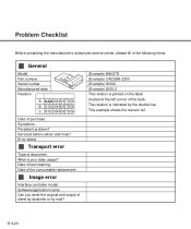
The revision is indicated by mail? (Example) M4097D (Example) CA02956-2300 (Example) 00002 (Example) 2000-2 The revision is your daily usage? Serviced before (when and how)? Date of document. This example shows the ... send the original and output of the back. Problem Checklist Before contacting the manufacturer's authorized service center, please fill in the following items. General Model Part number Serial number Manufactured data Revision A 0123456789 B 0123456789 C 0123456789 Date of the consumable replacement. Date of purchase Symptoms Persistent problem?
The revision is indicated by mail? (Example) M4097D (Example) CA02956-2300 (Example) 00002 (Example) 2000-2 The revision is your daily usage? Serviced before (when and how)? Date of document. This example shows the ... send the original and output of the back. Problem Checklist Before contacting the manufacturer's authorized service center, please fill in the following items. General Model Part number Serial number Manufactured data Revision A 0123456789 B 0123456789 C 0123456789 Date of the consumable replacement. Date of purchase Symptoms Persistent problem?

Operator's Guide
Page 3
... manual, may cause harmful interference to provide reasonable protection against harmful interference in accordance with the limits for compliance could void the user's authority to Part 15 of the power cord must be 3 meters (10 feet) or less.
... manual, may cause harmful interference to provide reasonable protection against harmful interference in accordance with the limits for compliance could void the user's authority to Part 15 of the power cord must be 3 meters (10 feet) or less.

Operator's Guide
Page 4
This Class B digital apparatus complies with Canadian ICES-003. As an ENERGYSTAR ® Partner, Fujitsu Limited has determined that this manual may be revised without permission. The contents of this manual may be reproduced in Japan. Printed in any form without prior notice. ii Cet appareil numérique de la classe B est conformme à la norme NMB-003 du Canada. S. All Rights Reserved, Copyright © 2000 FUJITSU LIMITED. No part of this scanner meets ENERGYSTAR ® guidelines for energy efficiency. registered mark. ENERGYSTAR ® is a U.
This Class B digital apparatus complies with Canadian ICES-003. As an ENERGYSTAR ® Partner, Fujitsu Limited has determined that this manual may be revised without permission. The contents of this manual may be reproduced in Japan. Printed in any form without prior notice. ii Cet appareil numérique de la classe B est conformme à la norme NMB-003 du Canada. S. All Rights Reserved, Copyright © 2000 FUJITSU LIMITED. No part of this scanner meets ENERGYSTAR ® guidelines for energy efficiency. registered mark. ENERGYSTAR ® is a U.


