
Cleaning & Maintenance
Page 8
CONTENTS CHAPTER 1 DESCRIPTION 1-1 Units 1-2 Assemblies 1-4 Operator panel 1-5 Panel Display 1-6 CHAPTER 2 CLEANING 2-1 Cleaning Supplies and Areas Requiring Cleaning .......... 2-2 Supplies 2-2 Areas Requiring Cleaning 2-3 Cleaning the ADF 2-4 Cleaning the Flatbed 2-10 CHAPTER 3 REPLACEMENT OF PARTS 3-1 Pad Assembly 3-2 Pick Roller 3-4 CHAPTER 4 TROUBLESHOOTING 4-1 Clearing Paper Jams 4-2 Initial Checks 4-3 Problem Checklist 4-20 vii
CONTENTS CHAPTER 1 DESCRIPTION 1-1 Units 1-2 Assemblies 1-4 Operator panel 1-5 Panel Display 1-6 CHAPTER 2 CLEANING 2-1 Cleaning Supplies and Areas Requiring Cleaning .......... 2-2 Supplies 2-2 Areas Requiring Cleaning 2-3 Cleaning the ADF 2-4 Cleaning the Flatbed 2-10 CHAPTER 3 REPLACEMENT OF PARTS 3-1 Pad Assembly 3-2 Pick Roller 3-4 CHAPTER 4 TROUBLESHOOTING 4-1 Clearing Paper Jams 4-2 Initial Checks 4-3 Problem Checklist 4-20 vii

Cleaning & Maintenance
Page 13
Assemblies Thumb screw Guide A ASY Stacker Pad ASY Pick roller 2 Pick roller 1 1-4
Assemblies Thumb screw Guide A ASY Stacker Pad ASY Pick roller 2 Pick roller 1 1-4
Cleaning & Maintenance
Page 22
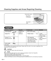
.... • Paper almost entirely covered with printing. • Paper with cleaner F2. Apply Cleaner F1 to cotton swab. Cleaner F1 or Isopropyl alcohol • PAD assembly Every 5,000 sheets • Pick roller/Feed rollers/ Glass/Sheet guide Every 5,000 sheets 1 bottle. Frequencies (*1)(*3) Remarks Cleaning paper Cleaner F2 Contact your dealer ...or distributor Every 5,000 sheets • Plastic rollers (*2) 1 bottle Apply Cleaner F2 to cloth. Cleaning Supplies and Areas Requiring Cleaning Document cover Document holding pad Document bed Supplies Cleaning Supplies Type No.
.... • Paper almost entirely covered with printing. • Paper with cleaner F2. Apply Cleaner F1 to cotton swab. Cleaner F1 or Isopropyl alcohol • PAD assembly Every 5,000 sheets • Pick roller/Feed rollers/ Glass/Sheet guide Every 5,000 sheets 1 bottle. Frequencies (*1)(*3) Remarks Cleaning paper Cleaner F2 Contact your dealer ...or distributor Every 5,000 sheets • Plastic rollers (*2) 1 bottle Apply Cleaner F2 to cloth. Cleaning Supplies and Areas Requiring Cleaning Document cover Document holding pad Document bed Supplies Cleaning Supplies Type No.

Cleaning & Maintenance
Page 25
CLEANING Cleaning the ADF with a Dry cloth or a Cloth with Cleaner F1 1 Pull the ADF lever to open the ADF. 2 Use a dry cloth or a cloth moistened with Cleaner F1 to catch the Pick spring when wiping. NOTE If the glass is dirty, the image may include black vertical stripes. Glass 2-5 Pad assembly Glass: Wipe the glass lightly. Pad assembly : Wipe the pad in a downward direction (as follows. Be careful not to softly remove dirt and dust as indicated by the arrow).
CLEANING Cleaning the ADF with a Dry cloth or a Cloth with Cleaner F1 1 Pull the ADF lever to open the ADF. 2 Use a dry cloth or a cloth moistened with Cleaner F1 to catch the Pick spring when wiping. NOTE If the glass is dirty, the image may include black vertical stripes. Glass 2-5 Pad assembly Glass: Wipe the glass lightly. Pad assembly : Wipe the pad in a downward direction (as follows. Be careful not to softly remove dirt and dust as indicated by the arrow).

Cleaning & Maintenance
Page 31
Pad Assembly Pick Roller 3-1 CHAPTER 3 REPLACEMENT OF PARTS This chapter describes how to replace the pad assembly and the pick roller.
Pad Assembly Pick Roller 3-1 CHAPTER 3 REPLACEMENT OF PARTS This chapter describes how to replace the pad assembly and the pick roller.

Cleaning & Maintenance
Page 32
Pick Arm 1 Pull the ADF lever to estimate when the Pad assembly needs replacement. WARNING Turn off the power before replacing the Pad Assembly. Use the Abrasion counter on the Operator panel to open the ADF. 2 Push the Pick Arm carefully. 3-2 The life span may be decreased by as much as half when carbonless paper is about 100,000 sheets or one year. Pad Assembly ADF lever Pad ASY (PA03951-0151) NOTE The life span of the pad assembly is read frequently.
Pick Arm 1 Pull the ADF lever to estimate when the Pad assembly needs replacement. WARNING Turn off the power before replacing the Pad Assembly. Use the Abrasion counter on the Operator panel to open the ADF. 2 Push the Pick Arm carefully. 3-2 The life span may be decreased by as much as half when carbonless paper is about 100,000 sheets or one year. Pad Assembly ADF lever Pad ASY (PA03951-0151) NOTE The life span of the pad assembly is read frequently.

Cleaning & Maintenance
Page 33
REPLACEMENT OF PARTS 3 Slide the Pad Assembly to the left photo. NOTE Fit the Pad assembly pin into the larger hole, then slide it to the right until it towards you. CAUTION Don't hold the sensor arm with the Pad assembly. Then, being careful not to the ADF in the reverse sequence of the Pad assembly as shown in the left and pull it stops. 5 Close the ADF. 3-3 Pad assembly 4 Attach the Pad Assembly to hook the Pad spring, remove the Pad Assembly. NOTE Hold both ends of step 3.
REPLACEMENT OF PARTS 3 Slide the Pad Assembly to the left photo. NOTE Fit the Pad assembly pin into the larger hole, then slide it to the right until it towards you. CAUTION Don't hold the sensor arm with the Pad assembly. Then, being careful not to the ADF in the reverse sequence of the Pad assembly as shown in the left and pull it stops. 5 Close the ADF. 3-3 Pad assembly 4 Attach the Pad Assembly to hook the Pad spring, remove the Pad Assembly. NOTE Hold both ends of step 3.

Cleaning & Maintenance
Page 52
Flatten the curl or use the Flatbed to read the document. 9 Symptom "Please clean Pick-roller" is displayed. YES Is the Pad assembly dirty or worn out? Is the Pick roller dirty? YES Clean or replace the Pad assembly. (See p. 3-2, p. 3-3) NO Contact the manufacturer's authorized service center. 4-12 YES Clean the Pick roller. (See p. 2-6) NO NO Do documents meet specification described in the Operator's Guide?
Flatten the curl or use the Flatbed to read the document. 9 Symptom "Please clean Pick-roller" is displayed. YES Is the Pad assembly dirty or worn out? Is the Pick roller dirty? YES Clean or replace the Pad assembly. (See p. 3-2, p. 3-3) NO Contact the manufacturer's authorized service center. 4-12 YES Clean the Pick roller. (See p. 2-6) NO NO Do documents meet specification described in the Operator's Guide?

Cleaning & Maintenance
Page 55
TROUBLESHOOTING NO Is the document stack less than 0.32" (8mm) in height? YES Is the Pad dirty? YES Replace the Pad assembly. (See p. 3-2) NO Contact the manufacturer's authorized service center. 4-15 Reduce the batch size of the documents. YES Clean the Pad assembly. (See p. 2-4) NO Is the Pad worn out?
TROUBLESHOOTING NO Is the document stack less than 0.32" (8mm) in height? YES Is the Pad dirty? YES Replace the Pad assembly. (See p. 3-2) NO Contact the manufacturer's authorized service center. 4-15 Reduce the batch size of the documents. YES Clean the Pad assembly. (See p. 2-4) NO Is the Pad worn out?

Cleaning & Maintenance
Page 56
Fan the documents before loading them on the ADF paper chute? Do the conditions of the NO documents meet the requirements described in the Operator's Guide? Flatten the curl or use the Flatbed to read the documents. Install it correctly. (See p. 3-2) YES 4-16 YES NO Is the Pad assembly installed correctly? 11 Symptom Mispick occurs frequently. YES Have the documents been NO fanned before loading, or reduce the batch size.
Fan the documents before loading them on the ADF paper chute? Do the conditions of the NO documents meet the requirements described in the Operator's Guide? Flatten the curl or use the Flatbed to read the documents. Install it correctly. (See p. 3-2) YES 4-16 YES NO Is the Pad assembly installed correctly? 11 Symptom Mispick occurs frequently. YES Have the documents been NO fanned before loading, or reduce the batch size.

Operator's Guide
Page 14
Refer to the operating position before the scanner can be used. Units 1 Document cover 4 Operator panel 3 Document holding pad 2 Document bed 5 Stacker 9 ADF lever 8 ADF paper chute 7 Operator panel 12 Third party slot 6 Power switch 11 Interface connector 10 Power inlet M4097D NOTICE The shipping lock must be switched to page 2-4. 1-2 This section also provides the name of the scanner. Units and Assemblies This section shows the exterior view and assemblies of each part and describes its functions.
Refer to the operating position before the scanner can be used. Units 1 Document cover 4 Operator panel 3 Document holding pad 2 Document bed 5 Stacker 9 ADF lever 8 ADF paper chute 7 Operator panel 12 Third party slot 6 Power switch 11 Interface connector 10 Power inlet M4097D NOTICE The shipping lock must be switched to page 2-4. 1-2 This section also provides the name of the scanner. Units and Assemblies This section shows the exterior view and assemblies of each part and describes its functions.

Operator's Guide
Page 16
Assemblies Thumb screw Guide A ASY Stacker Pad ASY Pick roller 2 Pick roller 1 1-4
Assemblies Thumb screw Guide A ASY Stacker Pad ASY Pick roller 2 Pick roller 1 1-4

Operator's Guide
Page 95
... the Setup mode 7-1 ADF 1-2, 1-3 ADF lever 1-2, 1-3 mode 1-6 paper chute 1-2 Alarm 1-10 Ambient condition 5-1 Arrangement 1-5 Assemblies 1-4 B Belt 5-3 Button /LED Function 1-6 C Cable connection 2-5 Carrier fixing bracket 2-4 Checking the components 1-1 Connecting the interface cable 2-6 the power cable 2-5 Consumables 5-3 Contents of the Setup mode 6-2 Conventions iii D Density 3-3, 3-4 Dimentions 5-1, 5-2 DLT (Double letter) 3-3 Document bed 1-2, 1-3 holding pad 1-2, 1-3 Quality 4-2 Size 4-1 type...
... the Setup mode 7-1 ADF 1-2, 1-3 ADF lever 1-2, 1-3 mode 1-6 paper chute 1-2 Alarm 1-10 Ambient condition 5-1 Arrangement 1-5 Assemblies 1-4 B Belt 5-3 Button /LED Function 1-6 C Cable connection 2-5 Carrier fixing bracket 2-4 Checking the components 1-1 Connecting the interface cable 2-6 the power cable 2-5 Consumables 5-3 Contents of the Setup mode 6-2 Conventions iii D Density 3-3, 3-4 Dimentions 5-1, 5-2 DLT (Double letter) 3-3 Document bed 1-2, 1-3 holding pad 1-2, 1-3 Quality 4-2 Size 4-1 type...
Operator's Guide
Page 96
...1-6 Memory cover 1-2, 1-3 status 6-2, 6-9 N Next button 1-6 O Offset setting 6-2, 6-7 Operation status 1-8 Operator's Guide 1-1 Operator panel 1-2, 1-5 Option 5-4 P Pad Assembly 5-3 Paper counter 1-7 direction 3-2 weight 4-2 Preface ii Pick roller 1-4, 5-3 start time 6-2, 6-6 Plain paper 4-2 Portrait 3-2 IN-2 Power cable 1-1, 2-5 consumption ...the IPC/Memory Status 6-9 S Scanner 1-1 Setting double feed detection 6-3 IPC preset mode 6-4 Offset 6-7 picking start time 6-6 SCSI-ID 6-9 time-out limit 6-7 Setup mode 6-1, 6-2 Simplex 3-2 Size 3-3 Specifications 5-1 Stacker 1-2, 2-7 Start button 1-5, ...
...1-6 Memory cover 1-2, 1-3 status 6-2, 6-9 N Next button 1-6 O Offset setting 6-2, 6-7 Operation status 1-8 Operator's Guide 1-1 Operator panel 1-2, 1-5 Option 5-4 P Pad Assembly 5-3 Paper counter 1-7 direction 3-2 weight 4-2 Preface ii Pick roller 1-4, 5-3 start time 6-2, 6-6 Plain paper 4-2 Portrait 3-2 IN-2 Power cable 1-1, 2-5 consumption ...the IPC/Memory Status 6-9 S Scanner 1-1 Setting double feed detection 6-3 IPC preset mode 6-4 Offset 6-7 picking start time 6-6 SCSI-ID 6-9 time-out limit 6-7 Setup mode 6-1, 6-2 Simplex 3-2 Size 3-3 Specifications 5-1 Stacker 1-2, 2-7 Start button 1-5, ...

