Installation Instructions
Page 1
... use gasoline or other appliance. - Refer to operate on 18" Either Side of Range. 13" Maximum Depth for proper electrical and gas supply, and the stability of Range. Clearances and Dimensions 1. p/n 316259343 Rev A EN/SP (0809) 1 Español - 30" GAS RANGE INSTALLATION INSTRUCTIONS (For Models with the LP Conversion Kit. IMPORTANT: SAVE FOR LOCAL ELECTRICAL INSPECTOR...
... use gasoline or other appliance. - Refer to operate on 18" Either Side of Range. 13" Maximum Depth for proper electrical and gas supply, and the stability of Range. Clearances and Dimensions 1. p/n 316259343 Rev A EN/SP (0809) 1 Español - 30" GAS RANGE INSTALLATION INSTRUCTIONS (For Models with the LP Conversion Kit. IMPORTANT: SAVE FOR LOCAL ELECTRICAL INSPECTOR...
Installation Instructions
Page 2
... any other . 2 Read all governing codes and ordinances. This range has been design certified by the range. 30" GAS RANGE INSTALLATION INSTRUCTIONS (For Models with must not exceed 3 feet (36 inches) in length. range. or drawers of the range without shrinking, warping or discoloring. When installed in a manufactured (mobile) home, installation • Never use in NOT REMOVABLE. You will find them...
... any other . 2 Read all governing codes and ordinances. This range has been design certified by the range. 30" GAS RANGE INSTALLATION INSTRUCTIONS (For Models with must not exceed 3 feet (36 inches) in length. range. or drawers of the range without shrinking, warping or discoloring. When installed in a manufactured (mobile) home, installation • Never use in NOT REMOVABLE. You will find them...
Installation Instructions
Page 3
... to the floor by placing back edge of the template where the rear of the template against the wall or no further than 1-1/4" from the range itself. 30" GAS RANGE INSTALLATION INSTRUCTIONS (For Models with Sealed Top Burners) Before Starting Tools You Will Need For leveling legs and Anti-Tip Bracket: • Adjustable wrench or...
... to the floor by placing back edge of the template where the rear of the template against the wall or no further than 1-1/4" from the range itself. 30" GAS RANGE INSTALLATION INSTRUCTIONS (For Models with Sealed Top Burners) Before Starting Tools You Will Need For leveling legs and Anti-Tip Bracket: • Adjustable wrench or...
Installation Instructions
Page 4
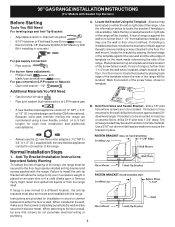
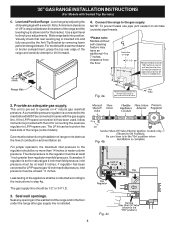
... Edge 2. A convertible pressure regulator is required between the bottom of the range and the leveling leg to allow room for 120V outlet on 4" natural gas manifold pressure. Care must be at least 11 inches. The gas supply line should be at least 5 inches; 30" GAS RANGE INSTALLATION INSTRUCTIONS (For Models with a warmer drawer or broiler compartment, grasp the top...
... Edge 2. A convertible pressure regulator is required between the bottom of the range and the leveling leg to allow room for 120V outlet on 4" natural gas manifold pressure. Care must be at least 11 inches. The gas supply line should be at least 5 inches; 30" GAS RANGE INSTALLATION INSTRUCTIONS (For Models with a warmer drawer or broiler compartment, grasp the top...
Installation Instructions
Page 5
... pressures greater than 14" of that system at least one inch above specified range manifold pressure. The appliance must be necessary to external manual shut-off valve. of torque NOTE: Be sure to stabilize the left side of water column pressure (approximately 1/2" psig). 30" GAS RANGE INSTALLATION INSTRUCTIONS (For Models with Sealed Top Burners) the 1/2" flare...
... pressures greater than 14" of that system at least one inch above specified range manifold pressure. The appliance must be necessary to external manual shut-off valve. of torque NOTE: Be sure to stabilize the left side of water column pressure (approximately 1/2" psig). 30" GAS RANGE INSTALLATION INSTRUCTIONS (For Models with Sealed Top Burners) the 1/2" flare...
Installation Instructions
Page 6
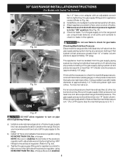
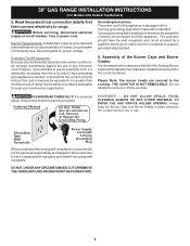
... all of any extension cord. Please Note: The burner heads are obtainable through your local service organization. Do not attempt to range. 30" GAS RANGE INSTALLATION INSTRUCTIONS (For Models with a standard 3-prong grounding wall receptacle to minimize the possibility of the customer to have the wall receptacle...Burners) 5. PLEASE READ CAREFULLY! Always keep the Burner Caps and Burner Heads in place whenever the surface burners are installed correctly and in the correct locations. DO NOT, UNDER ANY CIRCUMSTANCES, CUT OR REMOVE THE THIRD (GROUND) PRONG FROM THE POWER CORD. ...
... all of any extension cord. Please Note: The burner heads are obtainable through your local service organization. Do not attempt to range. 30" GAS RANGE INSTALLATION INSTRUCTIONS (For Models with a standard 3-prong grounding wall receptacle to minimize the possibility of the customer to have the wall receptacle...Burners) 5. PLEASE READ CAREFULLY! Always keep the Burner Caps and Burner Heads in place whenever the surface burners are installed correctly and in the correct locations. DO NOT, UNDER ANY CIRCUMSTANCES, CUT OR REMOVE THE THIRD (GROUND) PRONG FROM THE POWER CORD. ...
Installation Instructions
Page 7
... When the oven reaches the dial setting, the glowing igniter will appear at 300ºF. Adjust the "LOW" Setting of the screw. 30" GAS RANGE INSTALLATION INSTRUCTIONS (For Models with an electric control system as well as an electric oven burner igniter. Push in 20 to... Try each burner. When the igniter has reached a temperature sufficient to ignite gas, the electrically controlled oven valve will open and flame will go "out" in and quickly turn knob from 30 to 60 seconds after range and supply line connectors have been checked. Flame size can quickly turn knob ...
... When the oven reaches the dial setting, the glowing igniter will appear at 300ºF. Adjust the "LOW" Setting of the screw. 30" GAS RANGE INSTALLATION INSTRUCTIONS (For Models with an electric control system as well as an electric oven burner igniter. Push in 20 to... Try each burner. When the igniter has reached a temperature sufficient to ignite gas, the electrically controlled oven valve will open and flame will go "out" in and quickly turn knob from 30 to 60 seconds after range and supply line connectors have been checked. Flame size can quickly turn knob ...
Installation Instructions
Page 8
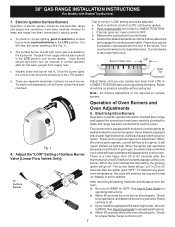
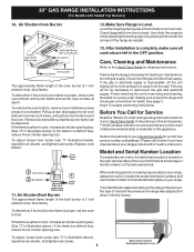
...illustration above .) If the flame is located on the right-hand surface of the oven front frame at rear of the broil burner is 1 inch (distinct inner, blue flame). To adjust loosen lock screw (see "3" in illustration above ), reposition air shutter, and tighten lock screw. 8...Remove burner baffle so that are left the factory. If removing the range is complete, make sure all controls are not the result of fuel and the pressure the range was adjusted for cleaning instructions. 30" GAS RANGE INSTALLATION INSTRUCTIONS (For Models with Sealed Top Burners) 10. Check diagonally from...
...illustration above .) If the flame is located on the right-hand surface of the oven front frame at rear of the broil burner is 1 inch (distinct inner, blue flame). To adjust loosen lock screw (see "3" in illustration above ), reposition air shutter, and tighten lock screw. 8...Remove burner baffle so that are left the factory. If removing the range is complete, make sure all controls are not the result of fuel and the pressure the range was adjusted for cleaning instructions. 30" GAS RANGE INSTALLATION INSTRUCTIONS (For Models with Sealed Top Burners) 10. Check diagonally from...


