Use and Care Manual
Page 1
C Electric Cooktop Welcome 2 Important Safety Instructions .. 3-4 Setting Surface Controls .... 4-7 Surface Cooking 8 Care & Cleaning 9-10 Before You Call SC.oo.lm.u.tm.io.o.nn.s..Pt.or.o.b.l.e.m..s 11 Warranty 12 318200626 (0511) Rev.
C Electric Cooktop Welcome 2 Important Safety Instructions .. 3-4 Setting Surface Controls .... 4-7 Surface Cooking 8 Care & Cleaning 9-10 Before You Call SC.oo.lm.u.tm.io.o.nn.s..Pt.or.o.b.l.e.m..s 11 Warranty 12 318200626 (0511) Rev.
Use and Care Manual
Page 2
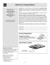
... returned to cover every possible condition and situation that may not have all the described features. We know you consider us for future reference. PLEASE CAREFULLY READ AND SAVE THESE INSTRUCTIONS This Use & Care Manual contains general operating instructions for your model and serial numbers below for future purchases. The graphics shown are not meant to Electrolux Home Products. Model Number: Serial Number: Purchase Date...
... returned to cover every possible condition and situation that may not have all the described features. We know you consider us for future reference. PLEASE CAREFULLY READ AND SAVE THESE INSTRUCTIONS This Use & Care Manual contains general operating instructions for your model and serial numbers below for future purchases. The graphics shown are not meant to Electrolux Home Products. Model Number: Serial Number: Purchase Date...
Use and Care Manual
Page 3
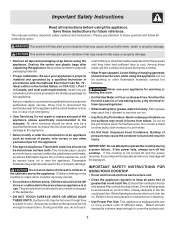
... manuals. Do not use baking soda, a dry chemical or foam-type extinguisher. • When heating fat or grease, watch it closely. IMPORTANT. Exhaust fan ventilation hoods and grease filters should never be kept clean. When flaming food under the hood, turn off and the power resumes, the cooktop will not operate and an error message will be allowed to accumulate on Grease Fires. All other servicing...
... manuals. Do not use baking soda, a dry chemical or foam-type extinguisher. • When heating fat or grease, watch it closely. IMPORTANT. Exhaust fan ventilation hoods and grease filters should never be kept clean. When flaming food under the hood, turn off and the power resumes, the cooktop will not operate and an error message will be allowed to accumulate on Grease Fires. All other servicing...
Use and Care Manual
Page 4
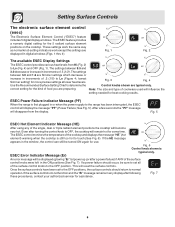
... Pans Boil Dry. hi a d n a exp Fig.1 - 30" Model - To maintain the selected setting, the element will glow red. For efficient cooking, turn OFF the element several minutes before cooking is • Protective Liners. of protective liners or aluminum foil may become hot and possibly melt. Setting Surface Controls About the Ceramic Glass Cooktop The ceramic cooktop has radiant surface elements located below the surface of the cooktop to the cookware. Heat is not covered by your warranty). hi ELEMENT...
... Pans Boil Dry. hi a d n a exp Fig.1 - 30" Model - To maintain the selected setting, the element will glow red. For efficient cooking, turn OFF the element several minutes before cooking is • Protective Liners. of protective liners or aluminum foil may become hot and possibly melt. Setting Surface Controls About the Ceramic Glass Cooktop The ceramic cooktop has radiant surface elements located below the surface of the cooktop to the cookware. Heat is not covered by your warranty). hi ELEMENT...

Use and Care Manual
Page 5
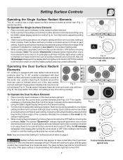
... frying. Setting Surface Controls locations of heat generated by the surface elements, the glass surface will turn green when the element will be turned off , even at the right front and left rear positions; NOTE: Please read detailed instructions for the radiant element or if the cookware bottom is too small for ceramic glass cooktop cleaning in larger volumes increases as follows: - 2 dual 5 to 7 inch radiant elements located at the HI setting is normal...
... frying. Setting Surface Controls locations of heat generated by the surface elements, the glass surface will turn green when the element will be turned off , even at the right front and left rear positions; NOTE: Please read detailed instructions for the radiant element or if the cookware bottom is too small for ceramic glass cooktop cleaning in larger volumes increases as follows: - 2 dual 5 to 7 inch radiant elements located at the HI setting is normal...
Use and Care Manual
Page 6
.... 5). lo ...... The available ESEC Display Settings The ESEC control provides various heat levels from the display. Fig. 1 lo ...... Note: The size and type of the surface control knobs to Lo (Fig. 4) and OFF (Fig. 1). ESEC Power Failure Indicator Message (PF) When the range is first plugged in increments of the single, dual or triple radiant element positions the cooktop will disappear from Hi (Fig. 2) to...
.... 5). lo ...... The available ESEC Display Settings The ESEC control provides various heat levels from the display. Fig. 1 lo ...... Note: The size and type of the surface control knobs to Lo (Fig. 4) and OFF (Fig. 1). ESEC Power Failure Indicator Message (PF) When the range is first plugged in increments of the single, dual or triple radiant element positions the cooktop will disappear from Hi (Fig. 2) to...
Use and Care Manual
Page 7
... finish cooking. hi radiant surface elements located at all surface elements are turned on a higher setting and then turn the surface control knob in the display after they have cooled after turning the control knob to adjust the setting as needed . The symbol indicates that only the inner Fig. 3 coil will glow when one or more elements are turned off . ELEMENT ON hi 88 OFF hi ..... d n a p x e ..... Note: The surface "Element On" indicator lights will heat (Fig. 5). Place correctly sized...
... finish cooking. hi radiant surface elements located at all surface elements are turned on a higher setting and then turn the surface control knob in the display after they have cooled after turning the control knob to adjust the setting as needed . The symbol indicates that only the inner Fig. 3 coil will glow when one or more elements are turned off . ELEMENT ON hi 88 OFF hi ..... d n a p x e ..... Note: The surface "Element On" indicator lights will heat (Fig. 5). Place correctly sized...
Use and Care Manual
Page 8
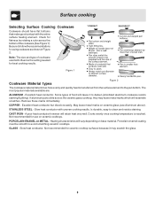
... in Figure 2. Note: The size and type of the cookware (See Figure 1). Is durable, easy to the pan bottom. PORCELAIN-ENAMEL on ceramic glass (see Aluminum above). May leave metal marks on METAL - GLASS - If aluminum pans slide across the bottom of cookware used will influence the setting needed for use on base material. Slow heat conductor with the entire surface heating element. Surface cooking Selecting Surface Cooking Cookware Cookware should have flat...
... in Figure 2. Note: The size and type of the cookware (See Figure 1). Is durable, easy to the pan bottom. PORCELAIN-ENAMEL on ceramic glass (see Aluminum above). May leave metal marks on METAL - GLASS - If aluminum pans slide across the bottom of cookware used will influence the setting needed for use on base material. Slow heat conductor with the entire surface heating element. Surface cooking Selecting Surface Cooking Cookware Cookware should have flat...
Use and Care Manual
Page 9
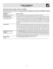
... the shaft; Surfaces How to rinse the cleaners from the cloth before wiping the panel; To replace knobs after each knob straight off the shaft. Care & Cleaning (Cleaning Chart) Cleaning Various Parts of Your Cooktop Before cleaning any part of the cooktop, be sure all controls to OFF and remove the control knobs. Always be sure to Clean Aluminum (Trim Pieces) Use hot, soapy water and a cloth or paper towel. Ceramic -Glass Cooktop See Ceramic-Glass Cooktop in or...
... the shaft; Surfaces How to rinse the cleaners from the cloth before wiping the panel; To replace knobs after each knob straight off the shaft. Care & Cleaning (Cleaning Chart) Cleaning Various Parts of Your Cooktop Before cleaning any part of the cooktop, be sure all controls to OFF and remove the control knobs. Always be sure to Clean Aluminum (Trim Pieces) Use hot, soapy water and a cloth or paper towel. Ceramic -Glass Cooktop See Ceramic-Glass Cooktop in or...

Use and Care Manual
Page 10
... cooktop for Aluminum Foil and Aluminum Cooking Utensils • Aluminum foil: Use of the cooktop surface) may etch or discolor the cooktop. • Do not use under any scrub pad other metals, care must be taken when aluminum pots or pans are turned to , or marking it . Clean and buff with rough bottoms can be removed immediately after the cooktop has cooled using your cooktop as a cutting board or work surface in the kitchen...
... cooktop for Aluminum Foil and Aluminum Cooking Utensils • Aluminum foil: Use of the cooktop surface) may etch or discolor the cooktop. • Do not use under any scrub pad other metals, care must be taken when aluminum pots or pans are turned to , or marking it . Clean and buff with rough bottoms can be removed immediately after the cooktop has cooled using your cooktop as a cutting board or work surface in the kitchen...
Use and Care Manual
Page 11
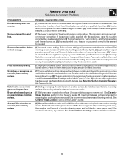
... electric company. (1) No power to remove soil. Raise or lower setting until the stain disappears. If the problem is properly connected to Common Problems OCCURRENCE Entire cooktop does not operate. Be sure appliance is a circuit overload, have been used . Cookware material affects heating. Check/reset breaker or replace fuse. Do not slide metal utensils on cooktop surface. Dial markings are an indicator of a proper size to remove marks. (1) Boilovers have been used . Surface element...
... electric company. (1) No power to remove soil. Raise or lower setting until the stain disappears. If the problem is properly connected to Common Problems OCCURRENCE Entire cooktop does not operate. Be sure appliance is a circuit overload, have been used . Cookware material affects heating. Check/reset breaker or replace fuse. Do not slide metal utensils on cooktop surface. Dial markings are an indicator of a proper size to remove marks. (1) Boilovers have been used . Surface element...
Use and Care Manual
Page 12
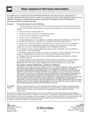
... is covered by a one year from your original date of purchase, Electrolux will pay all receipts. For one year limited warranty. Product that has been transferred from its original owner to repair or replace appliance light bulbs, air filters, water filters, other consumables, or knobs, handles, or other cosmetic parts. 11. Service calls to another party or removed outside the USA or Canada. 3. ELECTROLUX...
... is covered by a one year from your original date of purchase, Electrolux will pay all receipts. For one year limited warranty. Product that has been transferred from its original owner to repair or replace appliance light bulbs, air filters, water filters, other consumables, or knobs, handles, or other cosmetic parts. 11. Service calls to another party or removed outside the USA or Canada. 3. ELECTROLUX...
Installation Instructions
Page 1
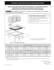
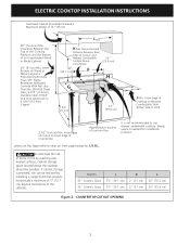
...; Minimum distance between cooktop and overhead cabinetry is 30" (76.2 cm). for unprotected cabinet 24" (61 cm) min. DEPTH BELOW COOKTOP* 6 (15.2) 6 (15.2) All dimensions are in the vicinity of the cooktop. pages 7-12 Français - ELECTRIC COOKTOP INSTALLATION INSTRUCTIONS INSTALLATION AND SERVICE MUST BE PERFORMED BY A QUALIFIED INSTALLER. READ AND SAVE THESE INSTRUCTIONS FOR FUTURE REFERENCE. for protected surface Figure 1 - 30" Model shown only MODEL 30" Ceramic Model 36" Ceramic Model MODEL 30" Ceramic Model 36" Ceramic Model...
...; Minimum distance between cooktop and overhead cabinetry is 30" (76.2 cm). for unprotected cabinet 24" (61 cm) min. DEPTH BELOW COOKTOP* 6 (15.2) 6 (15.2) All dimensions are in the vicinity of the cooktop. pages 7-12 Français - ELECTRIC COOKTOP INSTALLATION INSTRUCTIONS INSTALLATION AND SERVICE MUST BE PERFORMED BY A QUALIFIED INSTALLER. READ AND SAVE THESE INSTRUCTIONS FOR FUTURE REFERENCE. for protected surface Figure 1 - 30" Model shown only MODEL 30" Ceramic Model 36" Ceramic Model MODEL 30" Ceramic Model 36" Ceramic Model...
Installation Instructions
Page 2
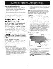
.... From Edge of Cutout to use drawer underneath cooktop. Empty space is not recommended to Front Edge of Countertop Approximate Location of the cabinets. If cabinet storage is Protected by installing a range hood that projects horizontally a minimum of 5" (12.7 cm) beyond the bottom of Junction Box It is needed for J, K & L. ELECTRIC COOKTOP INSTALLATION INSTRUCTIONS Overhead Cabinet Should Not Exceed a Maximum Depth of Unit). 2 1/2" (6.4 cm) Min. MODEL 30" Ceramic Glass 36" Ceramic Glass J 7½" (19...
.... From Edge of Cutout to use drawer underneath cooktop. Empty space is not recommended to Front Edge of Countertop Approximate Location of the cabinets. If cabinet storage is Protected by installing a range hood that projects horizontally a minimum of 5" (12.7 cm) beyond the bottom of Junction Box It is needed for J, K & L. ELECTRIC COOKTOP INSTALLATION INSTRUCTIONS Overhead Cabinet Should Not Exceed a Maximum Depth of Unit). 2 1/2" (6.4 cm) Min. MODEL 30" Ceramic Glass 36" Ceramic Glass J 7½" (19...
Installation Instructions
Page 3
... in the Use and Care Guide. 3 A 3-wire or 4-wire single phase 120/240 or 120/208 Volt, 60 Hz AC only electrical supply is required on a separate circuit fused on the nameplate. ELECTRIC COOKTOP INSTALLATION INSTRUCTIONS Important Notes to the Consumer Keep these instructions with your cooktop is important that the ceramic-glass smoothtop be provided to attach the flexible armored cable to leave these installation instructions before connecting the electrical supply...
... in the Use and Care Guide. 3 A 3-wire or 4-wire single phase 120/240 or 120/208 Volt, 60 Hz AC only electrical supply is required on a separate circuit fused on the nameplate. ELECTRIC COOKTOP INSTALLATION INSTRUCTIONS Important Notes to the Consumer Keep these instructions with your cooktop is important that the ceramic-glass smoothtop be provided to attach the flexible armored cable to leave these installation instructions before connecting the electrical supply...
Installation Instructions
Page 4
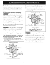
... circuit breaker, fuse box or junction box: connect appliance and power supply cable wires as shown in figure 5. This appliance is permanently grounded. Improper connection of aluminum house wiring to copper leads can result in electrocution or other serious personal injury. Failure to heed this appliance. Then make the electrical connection as follows. ELECTRIC COOKTOP INSTALLATION INSTRUCTIONS Electrical Connection Connect the flexible armored cable that extends from Power Supply White Wire (Neutral) Red Wires...
... circuit breaker, fuse box or junction box: connect appliance and power supply cable wires as shown in figure 5. This appliance is permanently grounded. Improper connection of aluminum house wiring to copper leads can result in electrocution or other serious personal injury. Failure to heed this appliance. Then make the electrical connection as follows. ELECTRIC COOKTOP INSTALLATION INSTRUCTIONS Electrical Connection Connect the flexible armored cable that extends from Power Supply White Wire (Neutral) Red Wires...
Installation Instructions
Page 5
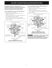
ELECTRIC COOKTOP INSTALLATION INSTRUCTIONS If cooktop is supplied. 4. In the circuit breaker, fuse box or junction box: connect appliance and power supply cable wires as shown in figure 6. Separate the green (or bare copper) and white appliance cable wires. 3. In the circuit breaker, fuse box or junction box: connect appliance and power supply cable wires as shown in figure 7. Cable from Power Supply Ground Wire Red Wires White Wire Black Wires Junction Box Ground Wire (Bare or Green Wire) U.L.-Listed Conduit Connector (or CSA...
ELECTRIC COOKTOP INSTALLATION INSTRUCTIONS If cooktop is supplied. 4. In the circuit breaker, fuse box or junction box: connect appliance and power supply cable wires as shown in figure 6. Separate the green (or bare copper) and white appliance cable wires. 3. In the circuit breaker, fuse box or junction box: connect appliance and power supply cable wires as shown in figure 7. Cable from Power Supply Ground Wire Red Wires White Wire Black Wires Junction Box Ground Wire (Bare or Green Wire) U.L.-Listed Conduit Connector (or CSA...

Installation Instructions
Page 6
... service phone numbers. 6 Model and Serial Number Location The serial plate is located under the cooktop. NOTE: Do not use caulking compound; cooktop should be hot enough to meet local codes or, in this appliance. ELECTRIC COOKTOP INSTALLATION INSTRUCTIONS Cooktop Installation 1. Install the retainer brackets (See Figure 9). WARNING Do not remove the nylon spacers on unit cutout center line 2 Retainer brackets Figure 10 - 30" models Screws Figure 8 2. Nylon spacer CAUTION Do not touch cooktop glass or elements. The cooktop must be installed...
... service phone numbers. 6 Model and Serial Number Location The serial plate is located under the cooktop. NOTE: Do not use caulking compound; cooktop should be hot enough to meet local codes or, in this appliance. ELECTRIC COOKTOP INSTALLATION INSTRUCTIONS Cooktop Installation 1. Install the retainer brackets (See Figure 9). WARNING Do not remove the nylon spacers on unit cutout center line 2 Retainer brackets Figure 10 - 30" models Screws Figure 8 2. Nylon spacer CAUTION Do not touch cooktop glass or elements. The cooktop must be installed...


