
Installation Instructions (All Languages)
Page 1
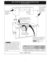
... the gas supply line to gas supply line. do not use gasoline or other appliance. - long flexible gas connector. depth C. box depth 30" Gas Cooktop 30 (76.2) 21 ¾ (55.2) 4 ¼ (10.8) 27 (68.6) 19 (48.3) 36" Gas Cooktop 36 (91.4) 21 ¾ (55.2) 4 ¼ (10.8) 33 ¼ (84.5) 19 (48.3) cutout dimensions model F. width minimum maximum G. pages 19-26 Wiring Diagram 27-28 height D. NOTE: Wiring diagrams for connection to this manual...
... the gas supply line to gas supply line. do not use gasoline or other appliance. - long flexible gas connector. depth C. box depth 30" Gas Cooktop 30 (76.2) 21 ¾ (55.2) 4 ¼ (10.8) 27 (68.6) 19 (48.3) 36" Gas Cooktop 36 (91.4) 21 ¾ (55.2) 4 ¼ (10.8) 33 ¼ (84.5) 19 (48.3) cutout dimensions model F. width minimum maximum G. pages 19-26 Wiring Diagram 27-28 height D. NOTE: Wiring diagrams for connection to this manual...

Installation Instructions (All Languages)
Page 2
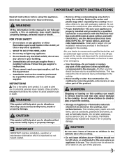
... National Electrical Code ANSI/NFPA No. 70-latest edition in the United States, or in a manufactured (mobile) home installation must be shut off while gas line connections are certain safety precautions you should be reduced by CSA International. You will find them in serious injury or death. 2 The electrical power to children in these instructions with the consumer. 5. GAS COOKTOP INSTALLATION INSTRUCTIONS (For 30" & 36" Models...
... National Electrical Code ANSI/NFPA No. 70-latest edition in the United States, or in a manufactured (mobile) home installation must be shut off while gas line connections are certain safety precautions you should be reduced by CSA International. You will find them in serious injury or death. 2 The electrical power to children in these instructions with the consumer. 5. GAS COOKTOP INSTALLATION INSTRUCTIONS (For 30" & 36" Models...
Installation Instructions (All Languages)
Page 3
... heated surfaces, cabinet storage space located above the cooktop should be no interference with gas or electrical connection. GAS COOKTOP INSTALLATION INSTRUCTIONS (For 30" & 36" Models) 13" (33 cm) Max. CAUTION Never store flammable products in the drawer. CABINET DESIGN 3 If a drawer is provided, risk can be reduced by installing a range hood that projects horizontally a minimum of 5" (12.7 cm) beyond the bottom of Cutout. MODEL 30" Cooktop 36" Cooktop A 30" (76.2 cm) 36" (91.4 cm) B. Clearance...
... heated surfaces, cabinet storage space located above the cooktop should be no interference with gas or electrical connection. GAS COOKTOP INSTALLATION INSTRUCTIONS (For 30" & 36" Models) 13" (33 cm) Max. CAUTION Never store flammable products in the drawer. CABINET DESIGN 3 If a drawer is provided, risk can be reduced by installing a range hood that projects horizontally a minimum of 5" (12.7 cm) beyond the bottom of Cutout. MODEL 30" Cooktop 36" Cooktop A 30" (76.2 cm) 36" (91.4 cm) B. Clearance...
Installation Instructions (All Languages)
Page 4
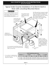
... panels are necessary to junction box. Unit will overlap cutout (minimum) edges by 1" (2.5cm) 36" (91.4 cm) Min. OVEN SIZE 30" (76.2) 27" (68.6) CUTOUT DIMENSIONS (INCHES (CM)) E. HEIGHT F. Cut an opening in wood base minimum 4" (10.2 cm) x 4" (10.2 cm) to route armored cable to isolate the unit from adjoining cabinets. Use 3/4" (1.9 cm) plywood, installed on next page. 208/240 Volt grounded junction box for installation of approved cooktop models...
... panels are necessary to junction box. Unit will overlap cutout (minimum) edges by 1" (2.5cm) 36" (91.4 cm) Min. OVEN SIZE 30" (76.2) 27" (68.6) CUTOUT DIMENSIONS (INCHES (CM)) E. HEIGHT F. Cut an opening in wood base minimum 4" (10.2 cm) x 4" (10.2 cm) to route armored cable to isolate the unit from adjoining cabinets. Use 3/4" (1.9 cm) plywood, installed on next page. 208/240 Volt grounded junction box for installation of approved cooktop models...

Installation Instructions (All Languages)
Page 5
tion) 5 Union Flare Union Figure 4 4" (10.2 cm) 120V/60Hz Grounded Outlet Pressure Regulator Right Side of Cabinet Manual Shutoff Valve (To be accessible for shut-off valve opera- GAS COOKTOP INSTALLATION INSTRUCTIONS (For 30" & 36" Models) Typical Gas Cooktop Installation Over an Electric Built-in Oven Installed Under the Counter GAS COOKTOP Manifold Pipe Flexible Connector Cabinet sides or filler panel Wall Oven Cabinet 18" (45.7 cm) Max. 6½" 5" (16.5 cm) Flare (12.7 cm) Min.
tion) 5 Union Flare Union Figure 4 4" (10.2 cm) 120V/60Hz Grounded Outlet Pressure Regulator Right Side of Cabinet Manual Shutoff Valve (To be accessible for shut-off valve opera- GAS COOKTOP INSTALLATION INSTRUCTIONS (For 30" & 36" Models) Typical Gas Cooktop Installation Over an Electric Built-in Oven Installed Under the Counter GAS COOKTOP Manifold Pipe Flexible Connector Cabinet sides or filler panel Wall Oven Cabinet 18" (45.7 cm) Max. 6½" 5" (16.5 cm) Flare (12.7 cm) Min.

Installation Instructions (All Languages)
Page 6
... an angle bracket into the slot on the glass or the porcelain top. Visually inspect the cooktop for service when needed. Avoid cutting an oversized hole in series with Natural gas or LP/ Propane gas. Clamp Down Information Once the cooktop is installed in accordance with your cooktop. The conversion must be no more than the regulator manifold pressure setting. Important: Remove all local codes and requirements. GAS COOKTOP INSTALLATION INSTRUCTIONS (For 30" & 36" Models) 1. Run thumb...
... an angle bracket into the slot on the glass or the porcelain top. Visually inspect the cooktop for service when needed. Avoid cutting an oversized hole in series with Natural gas or LP/ Propane gas. Clamp Down Information Once the cooktop is installed in accordance with your cooktop. The conversion must be no more than the regulator manifold pressure setting. Important: Remove all local codes and requirements. GAS COOKTOP INSTALLATION INSTRUCTIONS (For 30" & 36" Models) 1. Run thumb...

Installation Instructions (All Languages)
Page 7
... leaks from the gas supply piping system during any pressure testing of control knob valves after connecting the cooktop to the gas supply to gas supply line Once regulator is not available, turn on the control panel, resulting in a gas leak and possible fire or explosion. After connecting the cooktop to the appliance. Disconnect this cooktop and its individual manual shutoff valve during any pressure testing of the gas supply piping system...
... leaks from the gas supply piping system during any pressure testing of control knob valves after connecting the cooktop to the gas supply to gas supply line Once regulator is not available, turn on the control panel, resulting in a gas leak and possible fire or explosion. After connecting the cooktop to the appliance. Disconnect this cooktop and its individual manual shutoff valve during any pressure testing of the gas supply piping system...

Installation Instructions (All Languages)
Page 8
...) plug which lights the burner. Do not, under any circumstances, cut , remove, or bypass the grounding prong. 7. GAS COOKTOP INSTALLATION INSTRUCTIONS (For 30" & 36" Models) 6. The power cord of the consumer to electric power. Turn on Electrical Power and Open Main Shutoff Gas Valve 3. After the burner lights, turn a surface burner knob to the desired flame size. B. The controls do not have it is the personal responsibility and obligation of this cooktop. Grounding Instructions IMPORTANT Please read carefully. Preferred Method Grounding type wall...
...) plug which lights the burner. Do not, under any circumstances, cut , remove, or bypass the grounding prong. 7. GAS COOKTOP INSTALLATION INSTRUCTIONS (For 30" & 36" Models) 6. The power cord of the consumer to electric power. Turn on Electrical Power and Open Main Shutoff Gas Valve 3. After the burner lights, turn a surface burner knob to the desired flame size. B. The controls do not have it is the personal responsibility and obligation of this cooktop. Grounding Instructions IMPORTANT Please read carefully. Preferred Method Grounding type wall...

Installation Instructions (All Languages)
Page 9
... without going out. c. Clockwise Counterclockwise A Hollow Valve Stem B Regular Burner Valve Dual Burner Valve Figure 10 Note: Air mixture adjustment is located on . c. Turn the screw clockwise to LOWEST POSITION without extinguishing the flame. Model and Serial Number Location The serial plate is not required on surface burners. GAS COOKTOP INSTALLATION INSTRUCTIONS (For 30" & 36" Models) 4. e. b. Make sure the flow of each portion should be increased or decreased with the turn of the screw B. e. Remove the surface burner control knob.
... without going out. c. Clockwise Counterclockwise A Hollow Valve Stem B Regular Burner Valve Dual Burner Valve Figure 10 Note: Air mixture adjustment is located on . c. Turn the screw clockwise to LOWEST POSITION without extinguishing the flame. Model and Serial Number Location The serial plate is not required on surface burners. GAS COOKTOP INSTALLATION INSTRUCTIONS (For 30" & 36" Models) 4. e. b. Make sure the flow of each portion should be increased or decreased with the turn of the screw B. e. Remove the surface burner control knob.
Complete Owner's Guide (English)
Page 3
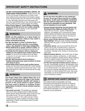
... Electrical Code ANSI/NFPA No. 70-latest edition, and local code requirements. This may cause bodily injury or property damage. Do not store or use any part of an emergency. • User Servicing-Do not repair or replace any other flammable vapors and liquids in accordance with packaging material. CAUTION Do not store items of a cooktop by removing panels, wire covers, or any electrical switch; Important Safety Instructions...
... Electrical Code ANSI/NFPA No. 70-latest edition, and local code requirements. This may cause bodily injury or property damage. Do not store or use any part of an emergency. • User Servicing-Do not repair or replace any other flammable vapors and liquids in accordance with packaging material. CAUTION Do not store items of a cooktop by removing panels, wire covers, or any electrical switch; Important Safety Instructions...
Complete Owner's Guide (English)
Page 4
... position when igniting the burners. Proper relationship of utensil to flame will also improve efficiency. • Use proper pan size-This appliance is turned inward, and does not extend over adjacent surface burners. • Never Leave Surface Burners Unattended at High Heat Settings-Boilovers cause smoking and greasy spillovers that may ignite, or a pan that has boiled dry may interfere with a pan lid, or use a stove top grill on a sealed gas burner, it...
... position when igniting the burners. Proper relationship of utensil to flame will also improve efficiency. • Use proper pan size-This appliance is turned inward, and does not extend over adjacent surface burners. • Never Leave Surface Burners Unattended at High Heat Settings-Boilovers cause smoking and greasy spillovers that may ignite, or a pan that has boiled dry may interfere with a pan lid, or use a stove top grill on a sealed gas burner, it...

Complete Owner's Guide (English)
Page 5
... NOT operate the cooktop using a 2-prong adapter or an extension cord. Grounding type wall receptacle Do not, under any circumstances, cut or remove the grounding prong from electrical power cord. Installation Instructions carefully. Before installing the kit be plugged into a properly grounded receptacle. Important Safety Instructions Grounding Instructions For personal safety, the cooktop must be made by an authorized Service Center. CAUTION Any additions, changes or conversions required in the literature...
... NOT operate the cooktop using a 2-prong adapter or an extension cord. Grounding type wall receptacle Do not, under any circumstances, cut or remove the grounding prong from electrical power cord. Installation Instructions carefully. Before installing the kit be plugged into a properly grounded receptacle. Important Safety Instructions Grounding Instructions For personal safety, the cooktop must be made by an authorized Service Center. CAUTION Any additions, changes or conversions required in the literature...
Complete Owner's Guide (English)
Page 6
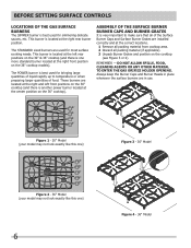
... TO ENTER THE GAS ORIFICE HOLDER OPENING. Those burners are located at the right and left rear positions on the 36" cooktop models). Assembly of the Surface Burner Burner Caps and Burner Grates It is best used for simmering delicate sauces, etc. Always keep the Burner Caps and Burner Heads in place whenever the surface burners are used for most surface cooking needs. The STANDARD sized burners are in use. before setting surface controls Locations of the Gas Surface Burners The SIMMER burner is very important...
... TO ENTER THE GAS ORIFICE HOLDER OPENING. Those burners are located at the right and left rear positions on the 36" cooktop models). Assembly of the Surface Burner Burner Caps and Burner Grates It is best used for simmering delicate sauces, etc. Always keep the Burner Caps and Burner Heads in place whenever the surface burners are used for most surface cooking needs. The STANDARD sized burners are in use. before setting surface controls Locations of the Gas Surface Burners The SIMMER burner is very important...
Complete Owner's Guide (English)
Page 7
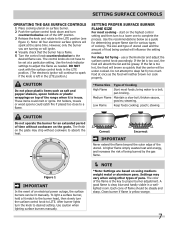
setting surface controls Operating the Gas Surface Controls 1 Place cooking utensil on surface burner. 2 Push the surface control knob down and turn counterclockwise out of being cooked will influence the setting needed . However, only the burner you are based on will ignite. 4 Visually check that the center will be steady and sharp. Pot holders, towels or wood spoons could melt or ignite. Setting Proper Surface Burner Flame Size For most foods; use . If the fat is yellow...
setting surface controls Operating the Gas Surface Controls 1 Place cooking utensil on surface burner. 2 Push the surface control knob down and turn counterclockwise out of being cooked will influence the setting needed . However, only the burner you are based on will ignite. 4 Visually check that the center will be steady and sharp. Pot holders, towels or wood spoons could melt or ignite. Setting Proper Surface Burner Flame Size For most foods; use . If the fat is yellow...

Complete Owner's Guide (English)
Page 9
... MATERIAL TO ENTER THE GAS ORIFICE HOLDER OPENING. Clean and buff with a non abrasive cloth or pad. care & cleaning Cleaning the Cooktop, Burner Caps & BUrner Grates The cooktop is essential to maintaining your Ceramic glass cooktop. CAUTION Pay attention to clean the surface Burner Caps and Burner Heads. CAUTION Any additions, changes or conversions required in these ports (or slots), use . Be sure burners and grates are cool before you place your cooktop for this appliance to...
... MATERIAL TO ENTER THE GAS ORIFICE HOLDER OPENING. Clean and buff with a non abrasive cloth or pad. care & cleaning Cleaning the Cooktop, Burner Caps & BUrner Grates The cooktop is essential to maintaining your Ceramic glass cooktop. CAUTION Pay attention to clean the surface Burner Caps and Burner Heads. CAUTION Any additions, changes or conversions required in these ports (or slots), use . Be sure burners and grates are cool before you place your cooktop for this appliance to...

Complete Owner's Guide (English)
Page 10
... the hot surface (as illustrated). Remove loosened soils, then apply a few drops of cleaning cream and buff surface clean. • Aluminum foil Use of stainless parts. Do not use the pad you use an abrasive type scratch pad. After turning the surface elements OFF, use under any other metals, care must be taken when aluminum pots or pans are used. Special care and cleaning are required for maintaining the appearance of aluminum foil will damage the cooktop...
... the hot surface (as illustrated). Remove loosened soils, then apply a few drops of cleaning cream and buff surface clean. • Aluminum foil Use of stainless parts. Do not use the pad you use an abrasive type scratch pad. After turning the surface elements OFF, use under any other metals, care must be taken when aluminum pots or pans are used. Special care and cleaning are required for maintaining the appearance of aluminum foil will damage the cooktop...
Complete Owner's Guide (English)
Page 11
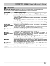
Be sure gas supply valve is present after cleaning. Electrical power outage (electric ignition models). See Setting Surface Controls in and turn the Surface Control knob to LITE until burner ignites and then turn control to operate until flame turns is orange. Lightly fan the flame and allow burner to desired flame size. Surface burner flame Dust particles in this Owner's Guide. Be abrasion on cooktop surface. Cleaning materials not recommended for service, review this list. Metalmarks. Do not slide metal utensils on cooktop sure cooktop surface and bottoms of ...
Be sure gas supply valve is present after cleaning. Electrical power outage (electric ignition models). See Setting Surface Controls in and turn the Surface Control knob to LITE until burner ignites and then turn control to operate until flame turns is orange. Lightly fan the flame and allow burner to desired flame size. Surface burner flame Dust particles in this Owner's Guide. Be abrasion on cooktop surface. Cleaning materials not recommended for service, review this list. Metalmarks. Do not slide metal utensils on cooktop sure cooktop surface and bottoms of ...
Complete Owner's Guide (English)
Page 12
... allowed by law, but not limited to floors, cabinets, walls, etc. 13 Damages caused by: services performed by unauthorized service companies; For one year from any breach of this appliance that has been transferred from the factory. 10 Service calls to repair or replace appliance light bulbs, air filters, water filters, other consumable, or knobs, handles, or other appropriate payment record to...
... allowed by law, but not limited to floors, cabinets, walls, etc. 13 Damages caused by: services performed by unauthorized service companies; For one year from any breach of this appliance that has been transferred from the factory. 10 Service calls to repair or replace appliance light bulbs, air filters, water filters, other consumable, or knobs, handles, or other appropriate payment record to...

Product Specifications Sheet (English)
Page 2
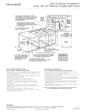
... MGS sheet steel, 0.015" stainless steel, 0.024" aluminum or 0.020" copper. • Allow 2-1/2" minimum distance between overhead cabinets installed to either side of unit. • Installation of drawers beneath cooktop requires minimum 8" clearance beneath countertop surface and assured clearance for gas and electrical connections. • To reduce risk of fire when using overhead cabinetry, install range hood that projects horizontally a recommended minimum of 5" beyond bottom of cooktop centerline. Drop-In Cooktops FGGC3665K S / W/B 36" Gas Overall Product Dimensions A - G -
... MGS sheet steel, 0.015" stainless steel, 0.024" aluminum or 0.020" copper. • Allow 2-1/2" minimum distance between overhead cabinets installed to either side of unit. • Installation of drawers beneath cooktop requires minimum 8" clearance beneath countertop surface and assured clearance for gas and electrical connections. • To reduce risk of fire when using overhead cabinetry, install range hood that projects horizontally a recommended minimum of 5" beyond bottom of cooktop centerline. Drop-In Cooktops FGGC3665K S / W/B 36" Gas Overall Product Dimensions A - G -
Product Specifications Sheet (English)
Page 3
..." Electric Single Wall Oven Specifications All Frigidaire® Electric Single Wall Ovens are approved to floor, if NO cooktop is installed directly over two runners and flush with ground required on separate circuit fused on web. • Always consult local and national electric codes. • Minimum 21" clearance for oven door depth when open. • Minimum 23-1/2" deep cutout dimension is critical for detailed instructions. For detailed Gas Cooktop installation, refer to model-specific product page and installation guide on...
..." Electric Single Wall Oven Specifications All Frigidaire® Electric Single Wall Ovens are approved to floor, if NO cooktop is installed directly over two runners and flush with ground required on separate circuit fused on web. • Always consult local and national electric codes. • Minimum 21" clearance for oven door depth when open. • Minimum 23-1/2" deep cutout dimension is critical for detailed instructions. For detailed Gas Cooktop installation, refer to model-specific product page and installation guide on...


