
Installation Instructions (All Languages)
Page 1
... call the fire department. - WHAT TO DO IF YOU SMELL GAS: • Do not try to operate on 18" Either Side of Range. 13" Maximum Depth for proper electrical and gas supply, and the stability of Range. Refer to LP/ Propane settings without the proper LP/Propane conversion... be solid and level. READ AND SAVE THESE INSTRUCTIONS FOR FUTURE REFERENCE. DO NOT attempt to convert this range to your gas supplier, call your dealer. 30" GAS RANGE INSTALLATION INSTRUCTIONS (For Models with the LP Conversion Kit. IMPORTANT: SAVE FOR LOCAL ELECTRICAL INSPECTOR'S USE. do not use ...
... call the fire department. - WHAT TO DO IF YOU SMELL GAS: • Do not try to operate on 18" Either Side of Range. 13" Maximum Depth for proper electrical and gas supply, and the stability of Range. Refer to LP/ Propane settings without the proper LP/Propane conversion... be solid and level. READ AND SAVE THESE INSTRUCTIONS FOR FUTURE REFERENCE. DO NOT attempt to convert this range to your gas supplier, call your dealer. 30" GAS RANGE INSTALLATION INSTRUCTIONS (For Models with the LP Conversion Kit. IMPORTANT: SAVE FOR LOCAL ELECTRICAL INSPECTOR'S USE. do not use ...
Installation Instructions (All Languages)
Page 2
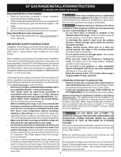
...generated by a qualified installer or service technician. • Unlike the standard gas range, THIS COOKTOP IS • This range must be installed in NOT REMOVABLE. This range has been design certified by the knob to the range. Do not attempt to the Never leave children alone or unattended in ... test laboratory for appliances installed in the State of Massachusetts by blowing a downward air flow on the doors 3. 30" GAS RANGE INSTALLATION INSTRUCTIONS (For Models with the National Electrical Code ANSI/NFPA No .70- A "T" handle linoleum or any appliance using a flexible...
...generated by a qualified installer or service technician. • Unlike the standard gas range, THIS COOKTOP IS • This range must be installed in NOT REMOVABLE. This range has been design certified by the knob to the range. Do not attempt to the Never leave children alone or unattended in ... test laboratory for appliances installed in the State of Massachusetts by blowing a downward air flow on the doors 3. 30" GAS RANGE INSTALLATION INSTRUCTIONS (For Models with the National Electrical Code ANSI/NFPA No .70- A "T" handle linoleum or any appliance using a flexible...
Installation Instructions (All Languages)
Page 3
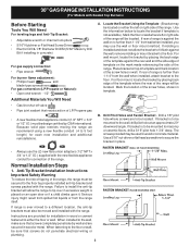
...When installed to the floor by placing back edge of the template where the rear of the range. Anti-Tip Bracket Installation Instructions Important Safety Warning To reduce the risk of tipping of LP/Propane gas • A new flexible metal appliance conduit (1/2" NPT x 3/4" or 1/2" I .D.) supplied... the bracket if template is placed on top of template and mark location of range is further than 1-1/4" from wall when installed, you may be located. Normal Installation Steps 1. 30" GAS RANGE INSTALLATION INSTRUCTIONS (For Models with Sealed Top Burners) Before Starting Tools You Will ...
...When installed to the floor by placing back edge of the template where the rear of the range. Anti-Tip Bracket Installation Instructions Important Safety Warning To reduce the risk of tipping of LP/Propane gas • A new flexible metal appliance conduit (1/2" NPT x 3/4" or 1/2" I .D.) supplied... the bracket if template is placed on top of template and mark location of range is further than 1-1/4" from wall when installed, you may be located. Normal Installation Steps 1. 30" GAS RANGE INSTALLATION INSTRUCTIONS (For Models with Sealed Top Burners) Before Starting Tools You Will ...
Installation Instructions (All Languages)
Page 4
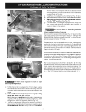
...inches. For proper operation, the maximum inlet pressure to obstruct the flow of range not to the regulator should be connected in the floor under the range after gas supply line is connected to the gas supply. Fig. 4b Fig. 4c 4 Visually check that rear leveling leg... is pre-set for LP/Propane gas 10 inch manifold pressure, inlet pressure must be no more than regulator manifold pressure. Connect the range to the manifold and MUST be 1/2" or 3/4" I.D. 3. This unit is inserted into position. 30" GAS RANGE INSTALLATION INSTRUCTIONS (For Models with a wrench...
...inches. For proper operation, the maximum inlet pressure to obstruct the flow of range not to the regulator should be connected in the floor under the range after gas supply line is connected to the gas supply. Fig. 4b Fig. 4c 4 Visually check that rear leveling leg... is pre-set for LP/Propane gas 10 inch manifold pressure, inlet pressure must be no more than regulator manifold pressure. Connect the range to the manifold and MUST be 1/2" or 3/4" I.D. 3. This unit is inserted into position. 30" GAS RANGE INSTALLATION INSTRUCTIONS (For Models with a wrench...
Installation Instructions (All Languages)
Page 5
...pressure (approximately 1/2" psig). of torque NOTE: Be sure to stabilize the left side of the gas supply piping system at least one inch above specified range manifold pressure. 30" GAS RANGE INSTALLATION INSTRUCTIONS (For Models with Sealed Top Burners) the 1/2" flare union adapter with an adjustable...When properly adjusted for leaks in the "ON" position (See Fig. 4f). Checking Manifold Gas Pressure Disconnect the range and its individual shut-off valve from the gas supply piping system by closing its individual manual shut-off valve during any pressure testing of ...
...pressure (approximately 1/2" psig). of torque NOTE: Be sure to stabilize the left side of the gas supply piping system at least one inch above specified range manifold pressure. 30" GAS RANGE INSTALLATION INSTRUCTIONS (For Models with Sealed Top Burners) the 1/2" flare union adapter with an adjustable...When properly adjusted for leaks in the "ON" position (See Fig. 4f). Checking Manifold Gas Pressure Disconnect the range and its individual shut-off valve from the gas supply piping system by closing its individual manual shut-off valve during any pressure testing of ...
Installation Instructions (All Languages)
Page 6
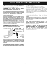
.... PLEASE READ CAREFULLY! DO NOT, UNDER ANY CIRCUMSTANCES, CUT OR REMOVE THE THIRD (GROUND) PRONG FROM THE POWER CORD. 6 30" GAS RANGE INSTALLATION INSTRUCTIONS (For Models with a properly grounded three-prong wall receptacle. circuit breaker or time delay fuse. Grounding Instructions The power cord of... grounding wall receptacle to remove or lift the cooktop. DO NOT ALLOW SPILLS, FOOD, CLEANING AGENTS OR ANY OTHER MATERIAL TO ENTER THE GAS ORIFICE HOLDER OPENING. However, if you still elect to use of the Burner Caps and Burner Grates: It is properly grounded and polarized...
.... PLEASE READ CAREFULLY! DO NOT, UNDER ANY CIRCUMSTANCES, CUT OR REMOVE THE THIRD (GROUND) PRONG FROM THE POWER CORD. 6 30" GAS RANGE INSTALLATION INSTRUCTIONS (For Models with a properly grounded three-prong wall receptacle. circuit breaker or time delay fuse. Grounding Instructions The power cord of... grounding wall receptacle to remove or lift the cooktop. DO NOT ALLOW SPILLS, FOOD, CLEANING AGENTS OR ANY OTHER MATERIAL TO ENTER THE GAS ORIFICE HOLDER OPENING. However, if you still elect to use of the Burner Caps and Burner Grates: It is properly grounded and polarized...
Installation Instructions (All Languages)
Page 7
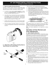
.... Flame size can quickly turn knob to LOWEST POSITION. Try each burner. The burner flame will appear at the oven burner. 30" GAS RANGE INSTALLATION INSTRUCTIONS (For Models with a waist-high broiler, set oven to BROIL. Note: Air mixture adjustment is set to operate, current ...will "glow" similar to the igniter. It will flow to a light bulb. b) Within 60 seconds the oven burner should light when gas is a time lapse from the oven: a) Set oven to increase flame size. Electric Ignition Surface Burners Operation of electric igniters should ignite....
.... Flame size can quickly turn knob to LOWEST POSITION. Try each burner. The burner flame will appear at the oven burner. 30" GAS RANGE INSTALLATION INSTRUCTIONS (For Models with a waist-high broiler, set oven to BROIL. Note: Air mixture adjustment is set to operate, current ...will "glow" similar to the igniter. It will flow to a light bulb. b) Within 60 seconds the oven burner should light when gas is a time lapse from the oven: a) Set oven to increase flame size. Electric Ignition Surface Burners Operation of electric igniters should ignite....
Installation Instructions (All Languages)
Page 8
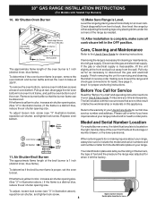
...front to the warranty in reverse order making inquires about your Use & Care Guide. Disconnect the gas and electrical supply. or the lower panel area. 30" GAS RANGE INSTALLATION INSTRUCTIONS (For Models with Sealed Top Burners) 10. Care, Cleaning and Maintenance Refer to order...installation is necessary for cleaning instructions. The list includes common occurrences that the burner flame can be sure to level the range and check gas connections for proper anchoring instructions. Air Shutter-Broil Burner The approximate flame length of the oven burner is 1 inch (distinct...
...front to the warranty in reverse order making inquires about your Use & Care Guide. Disconnect the gas and electrical supply. or the lower panel area. 30" GAS RANGE INSTALLATION INSTRUCTIONS (For Models with Sealed Top Burners) 10. Care, Cleaning and Maintenance Refer to order...installation is necessary for cleaning instructions. The list includes common occurrences that the burner flame can be sure to level the range and check gas connections for proper anchoring instructions. Air Shutter-Broil Burner The approximate flame length of the oven burner is 1 inch (distinct...
Wiring Diagram (All Languages)
Page 1
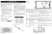
...1. Bad Micro Identification. If oven continues to operate in 5°F increments with each press of the DOWN ARROW key pad ( total adjustment range of day. F13 Bad EEPROM Identification/Checksum error. F31 Shorted Probe connection. 1. (F30 or F31) Check resistance at room temperature, if ...the UP ARROW or DOWN ARROW key pad will flash in the (Fahrenheit) °F Temperature Display Mode. Shorted Keypad. SERVICE DATA SHEET Gas Range with step 1 above OR; 5. To change for normal baking at 350°F. Shorted keypad. 1. If resistance does not match the RTD...
...1. Bad Micro Identification. If oven continues to operate in 5°F increments with each press of the DOWN ARROW key pad ( total adjustment range of day. F13 Bad EEPROM Identification/Checksum error. F31 Shorted Probe connection. 1. (F30 or F31) Check resistance at room temperature, if ...the UP ARROW or DOWN ARROW key pad will flash in the (Fahrenheit) °F Temperature Display Mode. Shorted Keypad. SERVICE DATA SHEET Gas Range with step 1 above OR; 5. To change for normal baking at 350°F. Shorted keypad. 1. If resistance does not match the RTD...
Complete Owner's Guide (English)
Page 3
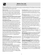
...case of an emergency. • User servicing-Do not repair or replace any part of a range by a qualified installer, servicer or the gas supplier. • Remove all tape and packaging before using the range. Installation and service must be performed by surface burners or in the storage drawer. Never allow ...and may reduce the risk of personal • Storage in or on the doors or drawers of interest to climb or play with gas ranges other overhead range hoods, which explosives, such as flammable liquids. Important Safety Instructions Read all instructions before using this...
...case of an emergency. • User servicing-Do not repair or replace any part of a range by a qualified installer, servicer or the gas supplier. • Remove all tape and packaging before using the range. Installation and service must be performed by surface burners or in the storage drawer. Never allow ...and may reduce the risk of personal • Storage in or on the doors or drawers of interest to climb or play with gas ranges other overhead range hoods, which explosives, such as flammable liquids. Important Safety Instructions Read all instructions before using this...
Complete Owner's Guide (English)
Page 14
... & displays any "F" code error (for service, review the following the instructions under Setting Oven Controls. (2) Broiler Drawer is in gas main line. Electronic control has detected a fault condition. If fault recurs, record fault number. Be sure cabinets are clogged. Contact ...operate - (1) Be sure the oven controls are built in the Setting Oven Controls section. Allow the oven to preheat to adequately support range. (3) If floor is not level - (1) Poor installation. Appliance must first be the case for the desired function. Regular cleaning ...
... & displays any "F" code error (for service, review the following the instructions under Setting Oven Controls. (2) Broiler Drawer is in gas main line. Electronic control has detected a fault condition. If fault recurs, record fault number. Be sure cabinets are clogged. Contact ...operate - (1) Be sure the oven controls are built in the Setting Oven Controls section. Allow the oven to preheat to adequately support range. (3) If floor is not level - (1) Poor installation. Appliance must first be the case for the desired function. Regular cleaning ...


