
Installation Instructions (All Languages)
Page 3
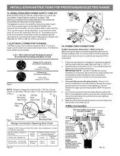
...install (Also see Figs. 9, 10 & 11). 2. Remove the factory installed ground screw & plate to Fig.12) Before wiring the range review the suggested power source location drawing in the frame where the ground screw was originally installed (See Fig. 12). 5. MODELS REQUIRING POWER ... Follow the manufacturer's installation instructions supplied with 1-3/8" dia. IMPORTANT NOTE: DO NOT LOOSEN the factory installed nut connections which secure the range wiring to a 4-Wire electrical system (new branch-circuit or mobile home requires 4-Wire connection): 1. The terminal block will then be...
...install (Also see Figs. 9, 10 & 11). 2. Remove the factory installed ground screw & plate to Fig.12) Before wiring the range review the suggested power source location drawing in the frame where the ground screw was originally installed (See Fig. 12). 5. MODELS REQUIRING POWER ... Follow the manufacturer's installation instructions supplied with 1-3/8" dia. IMPORTANT NOTE: DO NOT LOOSEN the factory installed nut connections which secure the range wiring to a 4-Wire electrical system (new branch-circuit or mobile home requires 4-Wire connection): 1. The terminal block will then be...
Installation Instructions (All Languages)
Page 4
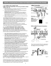
... ground strap from frame of electrical connection may occur if these 3 nuts are loosened or removed. 3. Wire Permanent Connection - Before wiring the range, review the suggested power source location drawings in the frame where the ground screw was originally installed. 5. (3 & 4 - NOTE: For 3-Wire ...install (Also see Figs. 9, 10 & 11). 2. Remove the factory installed ground screw & plate to the terminal block. Carefully slide range into final position while inserting rear leveling leg into final location. follow Steps 1,2 & 5 below . Tighten all the adequate clearances and ...
... ground strap from frame of electrical connection may occur if these 3 nuts are loosened or removed. 3. Wire Permanent Connection - Before wiring the range, review the suggested power source location drawings in the frame where the ground screw was originally installed. 5. (3 & 4 - NOTE: For 3-Wire ...install (Also see Figs. 9, 10 & 11). 2. Remove the factory installed ground screw & plate to the terminal block. Carefully slide range into final position while inserting rear leveling leg into final location. follow Steps 1,2 & 5 below . Tighten all the adequate clearances and ...
