

Installation Instructions
Page 1
... instructions with door handle 25-3/4" 48" maximum 49" door open maximum Fig. 1 Fig. 2 Fig. 3 30" *30" MINIMUM CLEARANCE BETWEEN THE TOP OF THE COOKING SURFACE AND THE BOTTOM OF AN UNPROTECTED WOOD OR METAL CABINET; When properly ...with your owner's guide for proper electrical supply, and the stability of range back. IMPORTANT: SAVE FOR LOCAL ELECTRICAL INSPECTOR'S USE. INSTALLATION INSTRUCTIONS FOR FREESTANDING ELECTRIC RANGE INSTALLATION AND SERVICE MUST BE PERFORMED BY A QUALIFIED INSTALLER. Clearances and Dimensions 1. Dimensions that are listed in the Use ...
... instructions with door handle 25-3/4" 48" maximum 49" door open maximum Fig. 1 Fig. 2 Fig. 3 30" *30" MINIMUM CLEARANCE BETWEEN THE TOP OF THE COOKING SURFACE AND THE BOTTOM OF AN UNPROTECTED WOOD OR METAL CABINET; When properly ...with your owner's guide for proper electrical supply, and the stability of range back. IMPORTANT: SAVE FOR LOCAL ELECTRICAL INSPECTOR'S USE. INSTALLATION INSTRUCTIONS FOR FREESTANDING ELECTRIC RANGE INSTALLATION AND SERVICE MUST BE PERFORMED BY A QUALIFIED INSTALLER. Clearances and Dimensions 1. Dimensions that are listed in the Use ...
Installation Instructions
Page 4
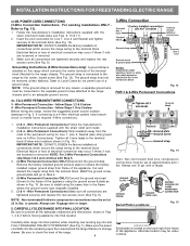
... nut connections which secure the range wiring to the terminal block. Be sure to an adequate ground source. 4c. 3 & 4-WIRE PERMANENT WIRE CONNECTIONS. 3 - Wire Permanent Connections) Make sure all the adequate clearances and dimensions shown in Fig. 15. Insert...& 4 - Fig. 14 Note: Non-terminated field wire compression connections must be set at approximately 22in./ lbs. INSTALLATION INSTRUCTIONS FOR FREESTANDING ELECTRIC RANGE or 4B. Grounding Instructions (3-Wire Connections only): A ground strap is removed for Line 1, Line 2 and Neutral and tighten securely to...
... nut connections which secure the range wiring to the terminal block. Be sure to an adequate ground source. 4c. 3 & 4-WIRE PERMANENT WIRE CONNECTIONS. 3 - Wire Permanent Connections) Make sure all the adequate clearances and dimensions shown in Fig. 15. Insert...& 4 - Fig. 14 Note: Non-terminated field wire compression connections must be set at approximately 22in./ lbs. INSTALLATION INSTRUCTIONS FOR FREESTANDING ELECTRIC RANGE or 4B. Grounding Instructions (3-Wire Connections only): A ground strap is removed for Line 1, Line 2 and Neutral and tighten securely to...
