
User manual
Page 2
... REPLACED BY AN INCORRECT TYPE DISPOSE OF USED BATTERIES ACCORDING TO THE INSTRUCTIONS © All rights reserved. All trade names are the property of their respective owners. Caution : refers to avoid problems. WEEE: The use NanoPC bet- All images are for reference only, please refer to use of this product is disposed of correctly, you to the physical product for nT-A3800...
... REPLACED BY AN INCORRECT TYPE DISPOSE OF USED BATTERIES ACCORDING TO THE INSTRUCTIONS © All rights reserved. All trade names are the property of their respective owners. Caution : refers to avoid problems. WEEE: The use NanoPC bet- All images are for reference only, please refer to use of this product is disposed of correctly, you to the physical product for nT-A3800...
User manual
Page 3
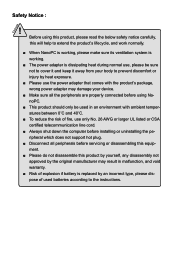
... does not support hot plug. ■ Disconnect all peripherals before servicing or disassembling this equipment. ■ Please do not disassemble this product by yourself, any disassembly not approved by the original manufacturer may result in malfunction, and void warranty. ■ Risk of explosion if battery is replaced by an incorrect type, please dispose of used batteries according to the instructions. CAUTION Safety...
... does not support hot plug. ■ Disconnect all peripherals before servicing or disassembling this equipment. ■ Please do not disassemble this product by yourself, any disassembly not approved by the original manufacturer may result in malfunction, and void warranty. ■ Risk of explosion if battery is replaced by an incorrect type, please dispose of used batteries according to the instructions. CAUTION Safety...
User manual
Page 4
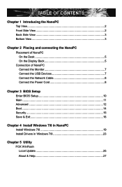
... View 3 Bottom View 3 Chapter 2 Placing and connecting the NanoPC Placement of NanoPC On the Desk 5 On the Display Back 5 Connection of NanoPC Connect the Monitor 7 Connect the USB Devices 7 Connect the Network Cable 8 Connect the Power Cord 8 Chapter 3 BIOS Setup Enter BIOS Setup 10 Main ...11 Advanced 12 Boot...14 Security 15 Save & Exit 16 Chapter 4 Install Windows 7/8 in NanoPC Install Windows 7/8 19 Install Drivers in Windows 7/8 23 Chapter 5 Utility FOX WinFlash Local Update 25 About & Help 27
... View 3 Bottom View 3 Chapter 2 Placing and connecting the NanoPC Placement of NanoPC On the Desk 5 On the Display Back 5 Connection of NanoPC Connect the Monitor 7 Connect the USB Devices 7 Connect the Network Cable 8 Connect the Power Cord 8 Chapter 3 BIOS Setup Enter BIOS Setup 10 Main ...11 Advanced 12 Boot...14 Security 15 Save & Exit 16 Chapter 4 Install Windows 7/8 in NanoPC Install Windows 7/8 19 Install Drivers in Windows 7/8 23 Chapter 5 Utility FOX WinFlash Local Update 25 About & Help 27
User manual
Page 7
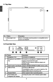
... Button Enter suspend mode in operating system 6 Power Button with Port optical connectors(3.5mm jack) SPDIF function requires additional adapter and adapter cable. 3 Multi-Function Card Reader Support SD/SDHC/MS/MS Pro/MMC memory cards 4 USB 3.0 Ports Connect to USB devices Caution:Before using it, you need to secure your NanoPC 1-2 Front Side View 24mm 1 2 3 4 5 6 No. Name Description 1 Headphone Port Connects to a headphone 2 Microphone In and SPDIF In Connects to a microphone or playback devices with Integrated LED Indicator Turning...
... Button Enter suspend mode in operating system 6 Power Button with Port optical connectors(3.5mm jack) SPDIF function requires additional adapter and adapter cable. 3 Multi-Function Card Reader Support SD/SDHC/MS/MS Pro/MMC memory cards 4 USB 3.0 Ports Connect to USB devices Caution:Before using it, you need to secure your NanoPC 1-2 Front Side View 24mm 1 2 3 4 5 6 No. Name Description 1 Headphone Port Connects to a headphone 2 Microphone In and SPDIF In Connects to a microphone or playback devices with Integrated LED Indicator Turning...
User manual
Page 8
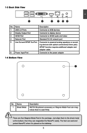
.... Just align them to the sheet metal on the tabletop. 3 Connects to powered analog speakers or recording devices with optical connectors(3.5mm jack) SPDIF function requires additional adapter and adapter cable. Name 1 USB 2.0 Ports 2 Display Output Port 3 HDMI Port 4 Network Port 5 Line Out and SPDIF Out Port 6 Power Input Port Description Connects to USB devices Connects to display device Connects to HDMI audio and video Standard RJ-45 network port Connects to the power adapter 1-4 Bottom View 1 CAUTION No. The feet can seat and protect...
.... Just align them to the sheet metal on the tabletop. 3 Connects to powered analog speakers or recording devices with optical connectors(3.5mm jack) SPDIF function requires additional adapter and adapter cable. Name 1 USB 2.0 Ports 2 Display Output Port 3 HDMI Port 4 Network Port 5 Line Out and SPDIF Out Port 6 Power Input Port Description Connects to USB devices Connects to display device Connects to HDMI audio and video Standard RJ-45 network port Connects to the power adapter 1-4 Bottom View 1 CAUTION No. The feet can seat and protect...
User manual
Page 12
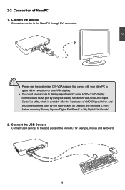
... on your VGA display. ■ You could have access to the USB ports of the NanoPC, for some HDTV or HD display connected via HDMI port by first right-clicking on Desktop and selecting it, then further choosing "Scaling Options(Digital Flat-Panel)" in "AMD VISION Engine Center", a utility, which is available after the installation of NanoPC 1. Connect the USB Devices Connect USB devices to display adjustment for example, mouse and keyboard. 7 And you...
... on your VGA display. ■ You could have access to the USB ports of the NanoPC, for some HDTV or HD display connected via HDMI port by first right-clicking on Desktop and selecting it, then further choosing "Scaling Options(Digital Flat-Panel)" in "AMD VISION Engine Center", a utility, which is available after the installation of NanoPC 1. Connect the USB Devices Connect USB devices to display adjustment for example, mouse and keyboard. 7 And you...
User manual
Page 13
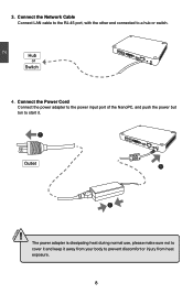
Connect the Network Cable Connect LAN cable to the RJ-45 port, with the other end connected to prevent discomfort or injury from heat exposure. 8 Hub or Switch 4. The power adapter is dissipating heat during normal use, please make sure not to cover it and keep it . 1 Outlet 3 2 ! Connect the Power Cord Connect the power adapter to the power input port of the NanoPC, and push the power but ton to start it away from your body to a hub or switch. 2 CAUTION 3.
Connect the Network Cable Connect LAN cable to the RJ-45 port, with the other end connected to prevent discomfort or injury from heat exposure. 8 Hub or Switch 4. The power adapter is dissipating heat during normal use, please make sure not to cover it and keep it . 1 Outlet 3 2 ! Connect the Power Cord Connect the power adapter to the power input port of the NanoPC, and push the power but ton to start it away from your body to a hub or switch. 2 CAUTION 3.

User manual
Page 14
... chapter tells how to change the default Item settings. An error message appears on the screen during the system Power On Self Test (POST) process. 2. We do not guarantee the content of the BIOS parameters are also provided. This chapter includes the following cases occur : 1. You have to run the Setup Program when the following information: ■ Enter BIOS Setup ■ Main ■ Advanced...
... chapter tells how to change the default Item settings. An error message appears on the screen during the system Power On Self Test (POST) process. 2. We do not guarantee the content of the BIOS parameters are also provided. This chapter includes the following cases occur : 1. You have to run the Setup Program when the following information: ■ Enter BIOS Setup ■ Main ■ Advanced...

User manual
Page 15
... set the boot device priority and enable "Quiet Boot" feature here. What you to key in correct password before boot or access to the submenu. Use the arrow right/left keys to select a specific function and go to Setup. Security The Administrator/User password can be set to maintain optimal system performance. You also can set up through this menu. You can save or discard the changes and exit BIOS setup...
... set the boot device priority and enable "Quiet Boot" feature here. What you to key in correct password before boot or access to the submenu. Use the arrow right/left keys to select a specific function and go to Setup. Security The Administrator/User password can be set to maintain optimal system performance. You also can set up through this menu. You can save or discard the changes and exit BIOS setup...
User manual
Page 16
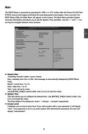
... 15:0109 Embedded Control Version 12.F1.08 System BIOS Version C74F1P01 CPU Information AMD E2-1800 APU with a user password, it will dispaly "User". 3 Main The BIOS Setup is automatically displayed by BIOS (Read Only). Use Tab to set the System Time and Date. Use [ENTER], [TAB] to select a field. Aptio Setup Utility - Date-date from 1 to configure the desired time. The Main Menu provides System Overview...
... 15:0109 Embedded Control Version 12.F1.08 System BIOS Version C74F1P01 CPU Information AMD E2-1800 APU with a user password, it will dispaly "User". 3 Main The BIOS Setup is automatically displayed by BIOS (Read Only). Use Tab to set the System Time and Date. Use [ENTER], [TAB] to select a field. Aptio Setup Utility - Date-date from 1 to configure the desired time. The Main Menu provides System Overview...

User manual
Page 17
... is used to enable or disable Deep Sleep Support function.When entering deep sleep mode system(S4/S5) only can select AHCI to support IDE mode. [AHCI Mode] - Copyright (C) 2012 American Megatrends, Inc. The Advanced Host Controller Interface (AHCI) specification describes the register level interface for a Host Controller for Serial ATA. Advanced Aptio Setup Utility - Copyright (C) 2012 American Megatrends, Inc. ► SATA Mode This item is used to enable or disable Onboard LAN / USB 3.0 Port...
... is used to enable or disable Deep Sleep Support function.When entering deep sleep mode system(S4/S5) only can select AHCI to support IDE mode. [AHCI Mode] - Copyright (C) 2012 American Megatrends, Inc. The Advanced Host Controller Interface (AHCI) specification describes the register level interface for a Host Controller for Serial ATA. Advanced Aptio Setup Utility - Copyright (C) 2012 American Megatrends, Inc. ► SATA Mode This item is used to enable or disable Onboard LAN / USB 3.0 Port...

User manual
Page 18
3 ► Restore on AC Power Loss This item is used to set which state the PC will take with when it resumes after an AC power loss. ► Supporting C6 power Loss This item is used to enable or disable C6 power state,which is featured in Fusion processors. ► Integrated GPU UMA Frame Buffer This item is used to set Integrate Graphics UMA Frame Buffer Size. 13
3 ► Restore on AC Power Loss This item is used to set which state the PC will take with when it resumes after an AC power loss. ► Supporting C6 power Loss This item is used to enable or disable C6 power state,which is featured in Fusion processors. ► Integrated GPU UMA Frame Buffer This item is used to set Integrate Graphics UMA Frame Buffer Size. 13

User manual
Page 19
.... The defaulte setting is [On]. ► Quiet Boot This item is used to enable or disable the quiet boot. [Disabled] : Displays the normal POST messages. [Enabled] : Displays OEM customer logo instead of devices required to launch active boot option. You can set the "Built-in EFI Shell" option boot priority in EFI Shell Support This item is used to set of POST messages. ► Fast Boot This item is used to control whether...
.... The defaulte setting is [On]. ► Quiet Boot This item is used to enable or disable the quiet boot. [Disabled] : Displays the normal POST messages. [Enabled] : Displays OEM customer logo instead of devices required to launch active boot option. You can set the "Built-in EFI Shell" option boot priority in EFI Shell Support This item is used to set of POST messages. ► Fast Boot This item is used to control whether...

User manual
Page 20
... 4 maximum length 20 Administrator Password User Password → ←: Select Screen ↑ ↓: Select Item Enter: Select +/-: Change Opt. After you to confirm the password. ► User Password This item is a power on password and must be entered to install or change administrator password. Main Advanced Boot Security Save & Exit Password Description Set Administrator Password If ONLY the Administrator's password is set , then this only limits access to Setup and is used to boot or enter Setup.
... 4 maximum length 20 Administrator Password User Password → ←: Select Screen ↑ ↓: Select Item Enter: Select +/-: Change Opt. After you to confirm the password. ► User Password This item is a power on password and must be entered to install or change administrator password. Main Advanced Boot Security Save & Exit Password Description Set Administrator Password If ONLY the Administrator's password is set , then this only limits access to Setup and is used to boot or enter Setup.

User manual
Page 21
... the menu. ► Save Changes and Reset If you select this motherboard. Select and press , it will be displayed in the screen. Main Advanced Boot Security Save & Exit Save Changes and Exit Discard Changes and Exit Save Changes and Reset Discard Changes and Reset Exit system setup after saving The changes Save Option Save Changes Discard Changes Restore Defaults Save as User Defaults Restore User Defaults Boot Override → ←: Select Screen ↑ ↓: Select Item Enter: Select +/-: Change...
... the menu. ► Save Changes and Reset If you select this motherboard. Select and press , it will be displayed in the screen. Main Advanced Boot Security Save & Exit Save Changes and Exit Discard Changes and Exit Save Changes and Reset Discard Changes and Reset Exit system setup after saving The changes Save Option Save Changes Discard Changes Restore Defaults Save as User Defaults Restore User Defaults Boot Override → ←: Select Screen ↑ ↓: Select Item Enter: Select +/-: Change...

User manual
Page 22
... to the menu. ► Boot Override BIOS auto detect the presence of connected devices, select the device you want to the menu. ► Restore User Defaults If you select this option and press , a message will directly boot from and press , then the system will be displayed in the screen. 3 By this default, BIOS have set cannot be supported by your hardware devices (for example, too many expansion cards were installed), the system...
... to the menu. ► Boot Override BIOS auto detect the presence of connected devices, select the device you want to the menu. ► Restore User Defaults If you select this option and press , a message will directly boot from and press , then the system will be displayed in the screen. 3 By this default, BIOS have set cannot be supported by your hardware devices (for example, too many expansion cards were installed), the system...

User manual
Page 24
... is set to turn on . ! ■ WiFi card with this package) 3. If there is no NETDVD in the BIOS setup. 4-1 Install Windows 7/8 1. Push power on button to "Disabled" in this package, you have these ready : 1. NanoPC USB Flash Disk (In this product doesn't support Vista operating system. ■ Windows 7(32-bit/64-bit) and Windows 8(32-bit) can't be installed when "Launch CSM" is an optional accessory. When the installation windows popup, Click...
... is set to turn on . ! ■ WiFi card with this package) 3. If there is no NETDVD in the BIOS setup. 4-1 Install Windows 7/8 1. Push power on button to "Disabled" in this package, you have these ready : 1. NanoPC USB Flash Disk (In this product doesn't support Vista operating system. ■ Windows 7(32-bit/64-bit) and Windows 8(32-bit) can't be installed when "Launch CSM" is an optional accessory. When the installation windows popup, Click...

User manual
Page 27
When the installation is complete. 22 4 10. The setup program will restart several times. 11. You can then follow the steps to install Windows 7/8 on your computer for it's first use. During the installa tion, your computer will then start to select system settings, create an account, set a password...etc, until the whole process is complete, setup will prepare your hard disk.
When the installation is complete. 22 4 10. The setup program will restart several times. 11. You can then follow the steps to install Windows 7/8 on your computer for it's first use. During the installa tion, your computer will then start to select system settings, create an account, set a password...etc, until the whole process is complete, setup will prepare your hard disk.

User manual
Page 28
Use these options to install all the drivers are installed, you have to restart your system. After all the drivers for a few seconds, the main menu will be displayed on each individual driver to install it manually. 4. When the Windows 7/8 is completely installed, you need to install the necessary drivers before using it. 23 Waiting for your NanoPC, then you can start using the NanoPC. Connet the USB Flash Disk.(USB Flash Disk in Windows 7/8 1. You must...
Use these options to install all the drivers are installed, you have to restart your system. After all the drivers for a few seconds, the main menu will be displayed on each individual driver to install it manually. 4. When the Windows 7/8 is completely installed, you need to install the necessary drivers before using it. 23 Waiting for your NanoPC, then you can start using the NanoPC. Connet the USB Flash Disk.(USB Flash Disk in Windows 7/8 1. You must...

User manual
Page 33
... and receiver. ▪ Connect the equipment into an outlet on a circuit different from all persons and must be installed to provide a separation distance of the FCC Rules. End-users and installers must not be installed and operated in accordance with provided instructions and the antenna(s) used in accordance with the instructions, may cause undesired operation. Caution: Any changes or modifications not...
... and receiver. ▪ Connect the equipment into an outlet on a circuit different from all persons and must be installed to provide a separation distance of the FCC Rules. End-users and installers must not be installed and operated in accordance with provided instructions and the antenna(s) used in accordance with the instructions, may cause undesired operation. Caution: Any changes or modifications not...


