User manual
Page 9
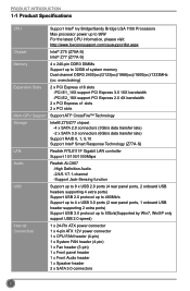
... power up to 95W For the latest CPU information, please visit: http://www.foxconnsupport.com/cpusupportlist.aspx Chipset Intel® Z75 (Z75A-S) Intel® Z77 (Z77A-S) Memory 4 x 240-pin DDR3 DIMMs Support up to 32GB of system memory Dual channel DDR3...RAID 0, 1, 5,10 Support Intel® Smart Response Technology (Z77A-S) LAN Realtek RTL8111F Gigabit LAN controller Support 10/100/1000Mbps Audio Realtek ALC887 -High Definition Audio -2/4/5.1/7.1-channel -Support Jack-Sensing function USB Support up to 8 x USB 2.0 ports (4 rear panel ports, 2 onboard USB headers supporting 4 ...
... power up to 95W For the latest CPU information, please visit: http://www.foxconnsupport.com/cpusupportlist.aspx Chipset Intel® Z75 (Z75A-S) Intel® Z77 (Z77A-S) Memory 4 x 240-pin DDR3 DIMMs Support up to 32GB of system memory Dual channel DDR3...RAID 0, 1, 5,10 Support Intel® Smart Response Technology (Z77A-S) LAN Realtek RTL8111F Gigabit LAN controller Support 10/100/1000Mbps Audio Realtek ALC887 -High Definition Audio -2/4/5.1/7.1-channel -Support Jack-Sensing function USB Support up to 8 x USB 2.0 ports (4 rear panel ports, 2 onboard USB headers supporting 4 ...
User manual
Page 12
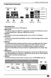
... 5 The HDMI Technology can support a maximum resolution of 1920x1080p but the actual resolutions supported depend on the monitor being used. 6. HDMI Port The HDMI (High-Definition Multimedia Interface) provides an all-digital audio/video interface to 10/100/1000Mb/s data rate. USB 2.0 Port The USB port supports the USB 2.0/1.1 specification. Use...
... 5 The HDMI Technology can support a maximum resolution of 1920x1080p but the actual resolutions supported depend on the monitor being used. 6. HDMI Port The HDMI (High-Definition Multimedia Interface) provides an all-digital audio/video interface to 10/100/1000Mb/s data rate. USB 2.0 Port The USB port supports the USB 2.0/1.1 specification. Use...
User manual
Page 13
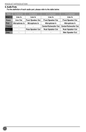
Rear Speaker Out Rear Speaker Out Rear Speaker Out Grey - - - Audio Ports For the definition of each audio port, please refer to the table below: Port 2-channel 4-channel 5.1-channel 7.1-channel Blue Line In Line In Line In Line In Green Line Out Front Speaker Out Front Speaker Out Front Speaker Out Pink Microphone In Microphone In Microphone In Microphone In Orange - - Side Speaker Out 6 PRODUCT INTRODUCTION 8. Center/Subwoofer Out Center/Subwoofer Out Black -
Rear Speaker Out Rear Speaker Out Rear Speaker Out Grey - - - Audio Ports For the definition of each audio port, please refer to the table below: Port 2-channel 4-channel 5.1-channel 7.1-channel Blue Line In Line In Line In Line In Green Line Out Front Speaker Out Front Speaker Out Front Speaker Out Pink Microphone In Microphone In Microphone In Microphone In Orange - - Side Speaker Out 6 PRODUCT INTRODUCTION 8. Center/Subwoofer Out Center/Subwoofer Out Black -
User manual
Page 21
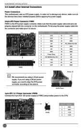
Make sure that the power supply cable and pins are using a 20-pin power supply, you using a 24-pin power supply. Pin # Definition Pin # Definition 1 3.3V 13 3.3V 2 3.3V 14 -12V 3 GND 15 GND 4 +5V 16 PS_ON(Soft On/Off) 5 GND 17 GND 6 +5V 18 GND 7 GND 19 GND 8 ... provides power to damage any device, make sure it is the ATX power supply connector. In order not to the CPU. 31 4 2 PWR2 Pin # 1 2 3 4 Definition GND GND +12V +12V 14 If you are properly aligned with the connector on the motherboard. Firmly plug the power supply cable into the connector...
Make sure that the power supply cable and pins are using a 20-pin power supply, you using a 24-pin power supply. Pin # Definition Pin # Definition 1 3.3V 13 3.3V 2 3.3V 14 -12V 3 GND 15 GND 4 +5V 16 PS_ON(Soft On/Off) 5 GND 17 GND 6 +5V 18 GND 7 GND 19 GND 8 ... provides power to damage any device, make sure it is the ATX power supply connector. In order not to the CPU. 31 4 2 PWR2 Pin # 1 2 3 4 Definition GND GND +12V +12V 14 If you are properly aligned with the connector on the motherboard. Firmly plug the power supply cable into the connector...