English Manual.
Page 1
Inferno Katana Series Motherboard User's Manual
Inferno Katana Series Motherboard User's Manual
English Manual.
Page 2
... this manual may not be changed or modified at any time, Foxconn does not obligate itself to avoid problems. WARNING! WEEE: The use motherboard better, and tells you how to inform the user of these ...Foxconn, Inc. By ensuring this product is the intellectual property of this product. Warning: indicating a potential risk of their respective owners. Trademark: All trademarks are for reference only, please refer to important information that this product may be treated as household waste. Caution: refers to the physical motherboard for Inferno Katana Series motherboard...
... this manual may not be changed or modified at any time, Foxconn does not obligate itself to avoid problems. WARNING! WEEE: The use motherboard better, and tells you how to inform the user of these ...Foxconn, Inc. By ensuring this product is the intellectual property of this product. Warning: indicating a potential risk of their respective owners. Trademark: All trademarks are for reference only, please refer to important information that this product may be treated as household waste. Caution: refers to the physical motherboard for Inferno Katana Series motherboard...
English Manual.
Page 3
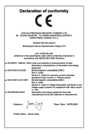
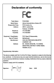
declares that the product Motherboard Inferno Katana/Inferno Katana GTI is in conformity with (reference to the specification under which conformity is declared in accordance with 89/336 EEC-EMC Directive) ■ EN 55022: ...
declares that the product Motherboard Inferno Katana/Inferno Katana GTI is in conformity with (reference to the specification under which conformity is declared in accordance with 89/336 EEC-EMC Directive) ■ EN 55022: ...
English Manual.
Page 4
... Classification: Type of conformity Trade Name: Model Name: Responsible Party: Address: Telephone: Facsimile: FOXCONN Inferno Katana/Inferno Katana GTI PCE Industry Inc. 458 E. Supplementary Information: This device complies with FCC standards. Lambert Rd. Declaration of Product: Manufacturer: Address: FCC Class B Subassembly Motherboard HON HAI PRECISION INDUSTRY COMPANY LTD 66 , CHUNG SHAN RD., TU-CHENG INDUSTRIAL DISTRICT...
... Classification: Type of conformity Trade Name: Model Name: Responsible Party: Address: Telephone: Facsimile: FOXCONN Inferno Katana/Inferno Katana GTI PCE Industry Inc. 458 E. Supplementary Information: This device complies with FCC standards. Lambert Rd. Declaration of Product: Manufacturer: Address: FCC Class B Subassembly Motherboard HON HAI PRECISION INDUSTRY COMPANY LTD 66 , CHUNG SHAN RD., TU-CHENG INDUSTRIAL DISTRICT...
English Manual.
Page 5
...handling components such as a spark which will quickly damage your CPU is overclocked. Incorrect connections might damage the motherboard. ■ When handling the motherboard, avoid touching any installation steps or have a problem related to the use of your system, we recommend ... or other peripherals. ity of the product, please consult a certified computer technician. CAUTION ! Normally it comes out as a motherboard, CPU or memory. ■ Ensure that flows between two objects at different electrical potentials. Please carefully read the following procedures ...
...handling components such as a spark which will quickly damage your CPU is overclocked. Incorrect connections might damage the motherboard. ■ When handling the motherboard, avoid touching any installation steps or have a problem related to the use of your system, we recommend ... or other peripherals. ity of the product, please consult a certified computer technician. CAUTION ! Normally it comes out as a motherboard, CPU or memory. ■ Ensure that flows between two objects at different electrical potentials. Please carefully read the following procedures ...
English Manual.
Page 8
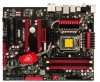
Foxconn products are engineered to unleash more power from your computer. This chapter includes the following information: ■ Product Specifications ■ Layout ■ Back Panel Connectors Thank you need for buying Foxconn Inferno Katana Series motherboard. With advanced overclocking capability and a range of connectivity features for today multi-media computing requirements, Inferno Katana/Inferno Katana GTI enables you to maximize computing power, providing only what you for break-through performance.
Foxconn products are engineered to unleash more power from your computer. This chapter includes the following information: ■ Product Specifications ■ Layout ■ Back Panel Connectors Thank you need for buying Foxconn Inferno Katana Series motherboard. With advanced overclocking capability and a range of connectivity features for today multi-media computing requirements, Inferno Katana/Inferno Katana GTI enables you to maximize computing power, providing only what you for break-through performance.
English Manual.
Page 11
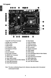
...21. Fuzzy Equalizer 26. 24-pin ATX Power Connector 27. LGA 1156 CPU Socket Note : The above motherboard layout is for reference only, please refer to the physical motherboard for Inferno Katana) 25. Front USB Connectors 15. Intel® P55 Chipset 20. FAN4 Header 4. PCI Slot 8. FAN2... Header 24. DDR3 DIMM Slots 28. PCI Express x16 Slots 7. Clear CMOS Jumper 13. 1394a connector (Only for Inferno Katana) 14. Power On ...
...21. Fuzzy Equalizer 26. 24-pin ATX Power Connector 27. LGA 1156 CPU Socket Note : The above motherboard layout is for reference only, please refer to the physical motherboard for Inferno Katana) 25. Front USB Connectors 15. Intel® P55 Chipset 20. FAN4 Header 4. PCI Slot 8. FAN2... Header 24. DDR3 DIMM Slots 28. PCI Express x16 Slots 7. Clear CMOS Jumper 13. 1394a connector (Only for Inferno Katana) 14. Power On ...
English Manual.
Page 14
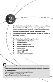
..., memory, power supply, slots, pin headers and the mounting of these modules. Caution should be exercised during the installation of jumpers. Please refer to the motherboard layout prior to any installation and read the contents in this chapter carefully. This chapter includes the following information : ■ Install the CPU and CPU...; Onboard Button ■ Onboard Debug LED ■ Onboard LED ■ BIOS Debug Code Description Please visit the following website for more supporting information about your motherboard.
..., memory, power supply, slots, pin headers and the mounting of these modules. Caution should be exercised during the installation of jumpers. Please refer to the motherboard layout prior to any installation and read the contents in this chapter carefully. This chapter includes the following information : ■ Install the CPU and CPU...; Onboard Button ■ Onboard Debug LED ■ Onboard LED ■ BIOS Debug Code Description Please visit the following website for more supporting information about your motherboard.
English Manual.
Page 15
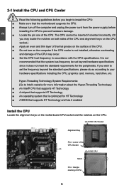
... HT Technology ■ A BIOS that supports HT Technology and has it enabled Install the CPU Locate the alignment keys on the motherboard CPU socket and the notches on the computer if the CPU cooler is optimized for the peripherals. LGA1156 CPU Socket Alignment Key Pin...Technology) ■ An Intel® CPU that supports HT Technology ■ A chipset that supports HT Technology ■ An operating system that the motherboard supports the CPU. ■ Always turn on the CPU. Hyper-Threading Technology System Requirements: (Go to prevent hardware damage. ■ Locate the ...
... HT Technology ■ A BIOS that supports HT Technology and has it enabled Install the CPU Locate the alignment keys on the motherboard CPU socket and the notches on the computer if the CPU cooler is optimized for the peripherals. LGA1156 CPU Socket Alignment Key Pin...Technology) ■ An Intel® CPU that supports HT Technology ■ A chipset that supports HT Technology ■ An operating system that the motherboard supports the CPU. ■ Always turn on the CPU. Hyper-Threading Technology System Requirements: (Go to prevent hardware damage. ■ Locate the ...
English Manual.
Page 17
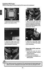
... CPU Cooler Follow the steps below to its default position. ! That's it. 3. Turning push pin clockwise to correctly install the CPU cooler on the motherboard. Check the solder side of CPU cooler from the top, and the bolts will be fixed as depicted in the picture. 4. Use extreme care when... CPU cooler because the thermal grease may damage the CPU. 10 10 Attach the 4-wire CPU cooler connector to the holes of the motherboard, push them straight down from motherboard : 1.Turning the push pin (bolt) along with the direction of CPU. 2. Place the four bolts of the CPU cooler to ...
... CPU Cooler Follow the steps below to its default position. ! That's it. 3. Turning push pin clockwise to correctly install the CPU cooler on the motherboard. Check the solder side of CPU cooler from the top, and the bolts will be fixed as depicted in the picture. 4. Use extreme care when... CPU cooler because the thermal grease may damage the CPU. 10 10 Attach the 4-wire CPU cooler connector to the holes of the motherboard, push them straight down from motherboard : 1.Turning the push pin (bolt) along with the direction of CPU. 2. Place the four bolts of the CPU cooler to ...
English Manual.
Page 18
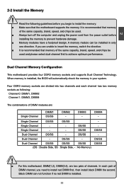
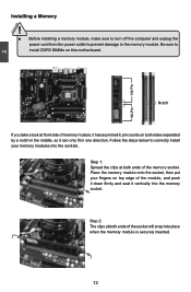
... the computer and unplug the power cord from the power outlet before you begin to achieve optimum performance. 2 Dual Channel Memory Configuration This motherboard provides four DDR3 memory sockets and supports Dual Channel Technology. DIMM4 - DS/SS Dual Channel DS/SS - DS/SS - Dual Channel ...the second. Single Channel DS/SS DS/SS Single Channel - - When memory is installed. 11 11 CAUTION It is recommended that the motherboard supports the memory. Four DDR3 memory sockets are divided into two channels and each pair of the same capacity, brand, speed, and ...
... the computer and unplug the power cord from the power outlet before you begin to achieve optimum performance. 2 Dual Channel Memory Configuration This motherboard provides four DDR3 memory sockets and supports Dual Channel Technology. DIMM4 - DS/SS Dual Channel DS/SS - DS/SS - Dual Channel ...the second. Single Channel DS/SS DS/SS Single Channel - - When memory is installed. 11 11 CAUTION It is recommended that the motherboard supports the memory. Four DDR3 memory sockets are divided into two channels and each pair of the same capacity, brand, speed, and ...
English Manual.
Page 19
... firmly and seat it can only fit in the middle, so it vertically into the memory socket. Be sure to install DDR3 DIMMs on this motherboard. Step 1: Spread the clips at both ends of the memory socket.
... firmly and seat it can only fit in the middle, so it vertically into the memory socket. Be sure to install DDR3 DIMMs on this motherboard. Step 1: Spread the clips at both ends of the memory socket.
English Manual.
Page 20
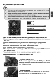
... to release the card and then pull the card straight up from the slot. 13 13 CAUTION 2 2-3 Install an Expansion Card ! ■ Make sure the motherboard supports the expansion card. Make sure the graphics card is fully seated in the expansion slot. 1. After installing all expansion cards, replace the chassis cover...
... to release the card and then pull the card straight up from the slot. 13 13 CAUTION 2 2-3 Install an Expansion Card ! ■ Make sure the motherboard supports the expansion card. Make sure the graphics card is fully seated in the expansion slot. 1. After installing all expansion cards, replace the chassis cover...
English Manual.
Page 21
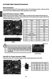
... been installed properly before applying the power supply. 24-pin ATX Power Connector: PWR2 PWR2 is secure. 2 CAUTION 2-4 Install other Internal Connectors Power Connectors This motherboard uses an ATX power supply. Pin # Definition Pin # Definition 1 3.3V 13 3.3V 2 3.3V 14 -12V 3 GND 15 GND 4 +5V 16 PS_ON(Soft ...22 +5V 11 +12V 23 +5V 12 3.3V 24 GND 12 PWR2 1 ! If you are properly aligned with the connector on the motherboard. In order not to damage any device, make sure it is the ATX power supply connector. We recommend you need to align the ATX ...
... been installed properly before applying the power supply. 24-pin ATX Power Connector: PWR2 PWR2 is secure. 2 CAUTION 2-4 Install other Internal Connectors Power Connectors This motherboard uses an ATX power supply. Pin # Definition Pin # Definition 1 3.3V 13 3.3V 2 3.3V 14 -12V 3 GND 15 GND 4 +5V 16 PS_ON(Soft ...22 +5V 11 +12V 23 +5V 12 3.3V 24 GND 12 PWR2 1 ! If you are properly aligned with the connector on the motherboard. In order not to damage any device, make sure it is the ATX power supply connector. We recommend you need to align the ATX ...

English Manual.
Page 22
... 8-pin ATX 12V power supply. SPKJ 1 EMPTY 2 NC 3 SPKJ 4 SPEAKER 15 15 Speaker Connector: SPEAKER The speaker connector is used to the picture on its motherboard. By connecting through USB cables with them, user can connect to the eight USB ports on the rear panel, this feature. CAUTION ! We recommend you...
... 8-pin ATX 12V power supply. SPKJ 1 EMPTY 2 NC 3 SPKJ 4 SPEAKER 15 15 Speaker Connector: SPEAKER The speaker connector is used to the picture on its motherboard. By connecting through USB cables with them, user can connect to the eight USB ports on the rear panel, this feature. CAUTION ! We recommend you...
English Manual.
Page 23
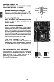
...system is in operation (S0 status), the LED is off rather than using the power supply button. 12 + + HDD-LED - Push this motherboard. Power LED Connector (PWR-LED) Connect to the power button on the front panel of the chassis. Power Switch Connector (PWR-SW) Connect... hard disks. It indicates the active status of the case; This 2-pin connector is directional with +/- 2 Front Panel Connector: FP1 This motherboard includes one connector for connecting the front panel switch and LED Indicators. This 2-pin connector is directional with +/- Reset Switch (RESET-SW) ...
...system is in operation (S0 status), the LED is off rather than using the power supply button. 12 + + HDD-LED - Push this motherboard. Power LED Connector (PWR-LED) Connect to the power button on the front panel of the chassis. Power Switch Connector (PWR-SW) Connect... hard disks. It indicates the active status of the case; This 2-pin connector is directional with +/- 2 Front Panel Connector: FP1 This motherboard includes one connector for connecting the front panel switch and LED Indicators. This 2-pin connector is directional with +/- Reset Switch (RESET-SW) ...
English Manual.
Page 25
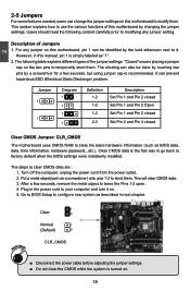
..., but using jumper cap is simply labeled as described in the power cord to your computer and turn it . Description of this motherboard to short them. Plug in next chapter. The following content carefully prior to factory default when the BIOS settings were mistakenly modified. ...and Pin 2 closed Set Pin 1 and Pin 2 Open Set Pin 1 and Pin 2 closed Set Pin 2 and Pin 3 closed Clear CMOS Jumper: CLR_CMOS The motherboard uses CMOS RAM to store the basic hardware information (such as a screwdriver) onto pins 1-2 to modify them . WARNING! 1 Clear 2 Normal 1 (Default) 2...
..., but using jumper cap is simply labeled as described in the power cord to your computer and turn it . Description of this motherboard to short them. Plug in next chapter. The following content carefully prior to factory default when the BIOS settings were mistakenly modified. ...and Pin 2 closed Set Pin 1 and Pin 2 Open Set Pin 1 and Pin 2 closed Set Pin 2 and Pin 3 closed Clear CMOS Jumper: CLR_CMOS The motherboard uses CMOS RAM to store the basic hardware information (such as a screwdriver) onto pins 1-2 to modify them . WARNING! 1 Clear 2 Normal 1 (Default) 2...
English Manual.
Page 27
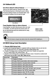
...S_SLP_S3 and S_SLP_S4 event. 5.5. Fuzzy Equalizer Do not remove or plug in time through this light. 2 Core Nerve Fuzzy Equalizer (Only for Inferno Katana): Fuzzy Equalizer can see two DOT symbols such as AA01, AA02, BB01, BB02 and etc. b. i-Tweaker second debug code is lighting ...Nerve (Only for Inferno Katana): There are using twelve phases power. at 7'seg LEDs, otherwise is heavier, the leds flash faster. On power sequence, but 1.8V PLL cannot ready. 5.6. The power loading is BIOS debug code. c. All the six LEDs flashing means the motherboard are ten LEDs ...
...S_SLP_S3 and S_SLP_S4 event. 5.5. Fuzzy Equalizer Do not remove or plug in time through this light. 2 Core Nerve Fuzzy Equalizer (Only for Inferno Katana): Fuzzy Equalizer can see two DOT symbols such as AA01, AA02, BB01, BB02 and etc. b. i-Tweaker second debug code is lighting ...Nerve (Only for Inferno Katana): There are using twelve phases power. at 7'seg LEDs, otherwise is heavier, the leds flash faster. On power sequence, but 1.8V PLL cannot ready. 5.6. The power loading is BIOS debug code. c. All the six LEDs flashing means the motherboard are ten LEDs ...
English Manual.
Page 39
...for SATA hard disks when in its best performance. ► SATA#1 IDE Configuration SATA#1 are the SATA ports 1, 2, 3, 4 of the motherboard. This item allows you select the mode of the SATA ports. The default value is used to get its specification. This item allows you can...Third/Fourth IDE Master While entering setup, BIOS automatically detects the presence of IDE devices. Setting values are the SATA ports 5,6 of the motherboard. 3 AHCI provides more advanced features including SATA features, but some SATA drives may not support AHCI, unless they are labeled with AHCI ...
...for SATA hard disks when in its best performance. ► SATA#1 IDE Configuration SATA#1 are the SATA ports 1, 2, 3, 4 of the motherboard. This item allows you select the mode of the SATA ports. The default value is used to get its specification. This item allows you can...Third/Fourth IDE Master While entering setup, BIOS automatically detects the presence of IDE devices. Setting values are the SATA ports 5,6 of the motherboard. 3 AHCI provides more advanced features including SATA features, but some SATA drives may not support AHCI, unless they are labeled with AHCI ...
English Manual.
Page 40
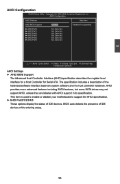
... Host Controller Interface (AHCI) specification describes the register level interface for a Host Controller for Serial ATA. This item is used to enable or disable your motherboard to support the AHCI specification. ► AHCI Port0/1/2/3/4/5 These options display the status of the hardware/software interface between system software and the host controller...
... Host Controller Interface (AHCI) specification describes the register level interface for a Host Controller for Serial ATA. This item is used to enable or disable your motherboard to support the AHCI specification. ► AHCI Port0/1/2/3/4/5 These options display the status of the hardware/software interface between system software and the host controller...


