English manual.
Page 6
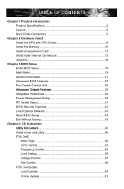
... Memory 10 Install an Expansion Card 12 Install other Internal Connectors 13 Jumpers 16 Chapter 3 BIOS Setup Enter BIOS Setup 19 Main Menu 19 System Information 21 Advanced BIOS Features 23 Fox Central Control Unit 25 ......A.d.v.a.n.ce.d..C.h.ip.s.e.t.F.e.a.tu.r.e.s 29 Integrated Peripherals 34 Power ...Management Setup 39 PC Health Status 41 BIOS Security Features 42 Load Optimal Defaults 43 Save & Exit Setup 43 Exit Without Saving 43 Chapter 4 CD Instruction ...
... Memory 10 Install an Expansion Card 12 Install other Internal Connectors 13 Jumpers 16 Chapter 3 BIOS Setup Enter BIOS Setup 19 Main Menu 19 System Information 21 Advanced BIOS Features 23 Fox Central Control Unit 25 ......A.d.v.a.n.ce.d..C.h.ip.s.e.t.F.e.a.tu.r.e.s 29 Integrated Peripherals 34 Power ...Management Setup 39 PC Health Status 41 BIOS Security Features 42 Load Optimal Defaults 43 Save & Exit Setup 43 Exit Without Saving 43 Chapter 4 CD Instruction ...
English manual.
Page 7
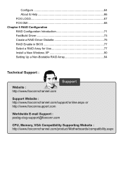
...66 FOX LOGO 67 FOX DMI 68 Chapter 5 RAID Configuration RAID Configuration Introduction 71 FastBuild Driver 73 Create a RAID Driver Diskette 75 RAID Enable in BIOS 77 Select a RAID Array for Use 77 Install a New Windows XP 90 Setting Up a Non-Bootable RAID Array 94 Technical Support : Website ...com Support Support Website : http://www.foxconnchannel.com/support/online.aspx or http://www.foxconnsupport.com Worldwide E-mail Support : pcebg-cisg-support@foxconn.com CPU, Memory, VGA Compatibility Supporting Website : http://www.foxconnchannel.com/product/Motherboards/compatibility.aspx
...66 FOX LOGO 67 FOX DMI 68 Chapter 5 RAID Configuration RAID Configuration Introduction 71 FastBuild Driver 73 Create a RAID Driver Diskette 75 RAID Enable in BIOS 77 Select a RAID Array for Use 77 Install a New Windows XP 90 Setting Up a Non-Bootable RAID Array 94 Technical Support : Website ...com Support Support Website : http://www.foxconnchannel.com/support/online.aspx or http://www.foxconnsupport.com Worldwide E-mail Support : pcebg-cisg-support@foxconn.com CPU, Memory, VGA Compatibility Supporting Website : http://www.foxconnchannel.com/product/Motherboards/compatibility.aspx
English manual.
Page 17
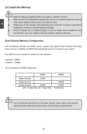
... prevent hardware damage. ■ Memory modules have a foolproof design. Read the following guidelines before installing the memory to achieve optimum performance. It is installed, the BIOS will automatically check the memory in only one direction. Single Channel - CAUTION 10 A memory module can be used . ■ Always turn off the computer and...
... prevent hardware damage. ■ Memory modules have a foolproof design. Read the following guidelines before installing the memory to achieve optimum performance. It is installed, the BIOS will automatically check the memory in only one direction. Single Channel - CAUTION 10 A memory module can be used . ■ Always turn off the computer and...
English manual.
Page 19
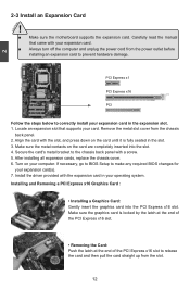
... contacts on your expansion card(s). 7. Turn on the card are completely inserted into the PCI Express x16 slot. If necessary, go to BIOS Setup to the chassis back panel with the expansion card in the expansion slot. 1. Remove the metal slot cover from the slot. 12... Secure the card's metal bracket to make any required BIOS changes for your computer. Install the driver provided with a screw. 5. 2 CAUTION 2-3 Install an Expansion Card ! ■ Make sure the motherboard supports...
... contacts on your expansion card(s). 7. Turn on the card are completely inserted into the PCI Express x16 slot. If necessary, go to BIOS Setup to the chassis back panel with the expansion card in the expansion slot. 1. Remove the metal slot cover from the slot. 12... Secure the card's metal bracket to make any required BIOS changes for your computer. Install the driver provided with a screw. 5. 2 CAUTION 2-3 Install an Expansion Card ! ■ Make sure the motherboard supports...
English manual.
Page 22
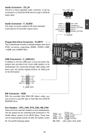
... : F_USB1/2/3 In addition to the four USB ports on the rear panel, this motherboard. These fans can be connected to any IDE type of the BIOS Setup. By connecting through a CD/DVD audio cable. D- 2 Audio Connector : CD_IN CD_IN is a Sony standard audio connector, it can be automatically turned off after the...
... : F_USB1/2/3 In addition to the four USB ports on the rear panel, this motherboard. These fans can be connected to any IDE type of the BIOS Setup. By connecting through a CD/DVD audio cable. D- 2 Audio Connector : CD_IN CD_IN is a Sony standard audio connector, it can be automatically turned off after the...
English manual.
Page 23
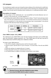
... setting. The shorting can also be identified by changing the jumper settings. The steps to factory default when the BIOS settings were mistakenly modified. Go to BIOS Setup to configure new system as BIOS data, date, time information, hardware password...etc.). However, in next chapter. 1 Clear 2 3 WARNING! 2 2-5 Jumpers For some features needed, users...
... setting. The shorting can also be identified by changing the jumper settings. The steps to factory default when the BIOS settings were mistakenly modified. Go to BIOS Setup to configure new system as BIOS data, date, time information, hardware password...etc.). However, in next chapter. 1 Clear 2 3 WARNING! 2 2-5 Jumpers For some features needed, users...
English manual.
Page 24
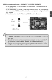
... up Jumpers: USBPWR1 / USBPWR2 / USBPWR3 1. At the same time, a corresponding setting must not exceed the power supply capability (+5VSB) whether under normal condition or in BIOS as below: Set "Power Management Setup" -> "Resume by USB Devices" to wake up the computer from S1 sleep mode using the connected USB devices. Set...
... up Jumpers: USBPWR1 / USBPWR2 / USBPWR3 1. At the same time, a corresponding setting must not exceed the power supply capability (+5VSB) whether under normal condition or in BIOS as below: Set "Power Management Setup" -> "Resume by USB Devices" to wake up the computer from S1 sleep mode using the connected USB devices. Set...
English manual.
Page 25
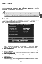
...65533;D�e�f�a�u�l�ts� ■ Save & Exit Setup ■ Exit Without Saving Since BIOS could be updated some other times, the BIOS information described in the future. You want to change the default CMOS settings. We do not guarantee the content of...time in this manual is available. Please visit our website for reference only. This chapter tells how to change system settings through the BIOS Setup menus. This chapter includes the following cases occur: 1. An error message appears on the screen during the system Power On Self...
...65533;D�e�f�a�u�l�ts� ■ Save & Exit Setup ■ Exit Without Saving Since BIOS could be updated some other times, the BIOS information described in the future. You want to change the default CMOS settings. We do not guarantee the content of...time in this manual is available. Please visit our website for reference only. This chapter tells how to change system settings through the BIOS Setup menus. This chapter includes the following cases occur: 1. An error message appears on the screen during the system Power On Self...
English manual.
Page 26
There are IDE devices, Super I /O and other USB devices... We do not suggest that you made. Each item in the BIOS Setup, and we shall not be set up the BIOS parameters is explained below: CMOS Setup Utility - Copyright (C) 1985-2005, American Megatrends, Inc. ► System Information ► PC ... a list of the screen, you to the sub-menu. They all can be viewed or set up through this menu. ► Advanced BIOS Features The advanced system features can press key to maintain optimal system performance. etc. 19 There are boot up settings. ► Fox Central ...
There are IDE devices, Super I /O and other USB devices... We do not suggest that you made. Each item in the BIOS Setup, and we shall not be set up the BIOS parameters is explained below: CMOS Setup Utility - Copyright (C) 1985-2005, American Megatrends, Inc. ► System Information ► PC ... a list of the screen, you to the sub-menu. They all can be viewed or set up through this menu. ► Advanced BIOS Features The advanced system features can press key to maintain optimal system performance. etc. 19 There are boot up settings. ► Fox Central ...
English manual.
Page 27
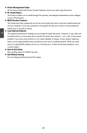
What you need now is heavy, set to prevent unauthorized use of your CPU/System. ► BIOS Security Features The Supervisor/User password can be set up through this menu. ► PC Health Status This setup enables you to read/change anything ... more memory or I /O cards, less memory ...etc.), still, it may sometimes come out an unstable system. It means, if your system loading is to adjust BIOS setting one by one, trial and error, to find out the best setting for your current system. ► Save & Exit Setup Save setting values to...
What you need now is heavy, set to prevent unauthorized use of your CPU/System. ► BIOS Security Features The Supervisor/User password can be set up through this menu. ► PC Health Status This setup enables you to read/change anything ... more memory or I /O cards, less memory ...etc.), still, it may sometimes come out an unstable system. It means, if your system loading is to adjust BIOS setting one by one, trial and error, to find out the best setting for your current system. ► Save & Exit Setup Save setting values to...
English manual.
Page 28
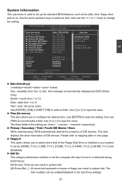
...65533;ID��E��M�a�s�t�e�r [Not Detected] select a field. Year-year, set up the standard BIOS features, such as the date, time, floppy drive and so on. This item displays the drive information of IDE devices. 3 ...;us� e D� isa� ble�d] � Flo�pp�y Di� sa� ble�d] Model Name BIOS ID : A78AX-S/A78AX-K : 79BF1P02 Move Enter:Select +/-/:Value F10:Save ESC:Exit F1:General Help F9:Optimized Defaults ► Date (mm:dd:yy) format. Month-month...
...65533;ID��E��M�a�s�t�e�r [Not Detected] select a field. Year-year, set up the standard BIOS features, such as the date, time, floppy drive and so on. This item displays the drive information of IDE devices. 3 ...;us� e D� isa� ble�d] � Flo�pp�y Di� sa� ble�d] Model Name BIOS ID : A78AX-S/A78AX-K : 79BF1P02 Move Enter:Select +/-/:Value F10:Save ESC:Exit F1:General Help F9:Optimized Defaults ► Date (mm:dd:yy) format. Month-month...
English manual.
Page 29
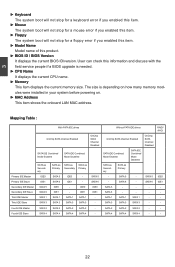
...1 SATA 3 IDE0 IDE1 SATA 1 SATA 3 OnChip SATA Channel Disabled SATA 5 SATA 6 IDE0 IDE1 - User can check this product. ► BIOS ID / BIOS Version It displays the current BIOS ID/version. Mapping Table : Primary IDE Master Primary IDE Slave Secondary IDE Master Secondary IDE Slave Third IDE Master Third IDE Slave...floppy error if you enabled this item. ► Model Name Model name of this information and discuss with the field service people if a BIOS upgrade is depending on how many memory modules were installed in your system before powering on. ► MAC Address This item shows the ...
...1 SATA 3 IDE0 IDE1 SATA 1 SATA 3 OnChip SATA Channel Disabled SATA 5 SATA 6 IDE0 IDE1 - User can check this product. ► BIOS ID / BIOS Version It displays the current BIOS ID/version. Mapping Table : Primary IDE Master Primary IDE Slave Secondary IDE Master Secondary IDE Slave Third IDE Master Third IDE Slave...floppy error if you enabled this item. ► Model Name Model name of this information and discuss with the field service people if a BIOS upgrade is depending on how many memory modules were installed in your system before powering on. ► MAC Address This item shows the ...
English manual.
Page 30
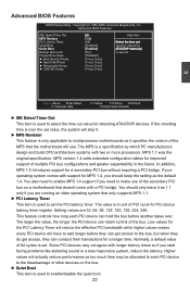
... so if you should only leave it specifies the version of multiple PCI bus configurations and greater expandability in the future. Advanced BIOS Features IDE Detect Time Out [5] Help Item M�P�S�R�ev�isi�on 1.�4] PCI Latency Timer ... an older operating system that only supports MPS 1.1. ► PCI Latency Timer This item is used to set the PCI latency timer. Advanced BIOS Features CMOS Setup Utility - Copyright (C) 1985-2005, American Megatrends, Inc. Floppy Drive Seek [Disabled] ► Boot Device Priority [Press Enter...
... so if you should only leave it specifies the version of multiple PCI bus configurations and greater expandability in the future. Advanced BIOS Features IDE Detect Time Out [5] Help Item M�P�S�R�ev�isi�on 1.�4] PCI Latency Timer ... an older operating system that only supports MPS 1.1. ► PCI Latency Timer This item is used to set the PCI latency timer. Advanced BIOS Features CMOS Setup Utility - Copyright (C) 1985-2005, American Megatrends, Inc. Floppy Drive Seek [Disabled] ► Boot Device Priority [Press Enter...
English manual.
Page 31
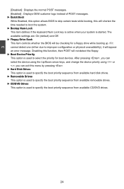
The available settings are: On (default) and Off. ► Floppy Drive Seek This item controls whether the BIOS will shorten the time needed to boot the system. ► Bootup Num-Lock This item defines if the keyboard Num Lock key is active when ... booting up. 3 [Disabled] : Displays the normal POST messages. [Enabled] : Displays OEM customer logo instead of POST messages. ► Quick Boot While Enabled, this option allows BIOS to skip certain tests while booting, this will be checking for boot devices. If it cannot detect one (either due to improper configuration or physical...
The available settings are: On (default) and Off. ► Floppy Drive Seek This item controls whether the BIOS will shorten the time needed to boot the system. ► Bootup Num-Lock This item defines if the keyboard Num Lock key is active when ... booting up. 3 [Disabled] : Displays the normal POST messages. [Enabled] : Displays OEM customer logo instead of POST messages. ► Quick Boot While Enabled, this option allows BIOS to skip certain tests while booting, this will be checking for boot devices. If it cannot detect one (either due to improper configuration or physical...
English manual.
Page 32
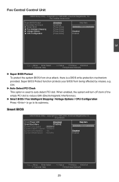
...;r�a�t�io�n� [Disabled] Help Item [Enabled] [Press Enter] Options [Press Enter] [Press Enter D�is a BIOS write-protection mechanism provided. Copyright (C) 1985-2005, American Megatrends, Inc. CIH. ► Auto Detect PCI Clock This option is � ...: 533 MHz Enabled Move Enter:Select +/-/:Value F10:Save ESC:Exit F1:General Help F9:Optimized Defaults 25 Super BIOS Protect function protects your BIOS from virus attack, there is �ab�le�d [Press Enter] Enabled 3 Move Enter:Select ...
...;r�a�t�io�n� [Disabled] Help Item [Enabled] [Press Enter] Options [Press Enter] [Press Enter D�is a BIOS write-protection mechanism provided. Copyright (C) 1985-2005, American Megatrends, Inc. CIH. ► Auto Detect PCI Clock This option is � ...: 533 MHz Enabled Move Enter:Select +/-/:Value F10:Save ESC:Exit F1:General Help F9:Optimized Defaults 25 Super BIOS Protect function protects your BIOS from virus attack, there is �ab�le�d [Press Enter] Enabled 3 Move Enter:Select ...
English manual.
Page 38
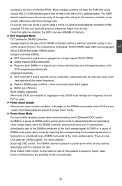
...] CKE control. A DIMM or a group of DIMMs enters power down mode by asserting the corresponding clock enable signal when a transaction is enabled, the BIOS can see 4096MB of ganged (128-bit DRAM data width) and unganged (64-bit DRAM data width) DRAM modes : Ganged channels (DDR2) : &#...chip select(s). 31 more concurrent open dram pages . ■ Better bus efficiency. Burst lengths supported When both DCTs are enabled in unganged mode, BIOS must initialize the frequency of both chan- Ganged refers to the use of each channel : [Channel] CKE control. The DRAM channel is enabled...
...] CKE control. A DIMM or a group of DIMMs enters power down mode by asserting the corresponding clock enable signal when a transaction is enabled, the BIOS can see 4096MB of ganged (128-bit DRAM data width) and unganged (64-bit DRAM data width) DRAM modes : Ganged channels (DDR2) : &#...chip select(s). 31 more concurrent open dram pages . ■ Better bus efficiency. Burst lengths supported When both DCTs are enabled in unganged mode, BIOS must initialize the frequency of both chan- Ganged refers to the use of each channel : [Channel] CKE control. The DRAM channel is enabled...
English manual.
Page 39
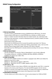
It contains important information about the module's speed, size, addressing mode and various other parameters, so that BIOS programs into the memory controller is a function of DRAM timing by SPD device. Select [Auto] for SPD enable mode. The value that the motherboard memory ... number of memory clocks it will appear only in AM2+ CPU. ► DRAM Timing Mode When both DCTs (DRAM controller) are enabled in unganged mode, BIOS must initialize the frequency of each DIMM. ► tRCD (RAS-to-CAS Delay) This item allows you to enable/disable provision of the target clock...
It contains important information about the module's speed, size, addressing mode and various other parameters, so that BIOS programs into the memory controller is a function of DRAM timing by SPD device. Select [Auto] for SPD enable mode. The value that the motherboard memory ... number of memory clocks it will appear only in AM2+ CPU. ► DRAM Timing Mode When both DCTs (DRAM controller) are enabled in unganged mode, BIOS must initialize the frequency of each DIMM. ► tRCD (RAS-to-CAS Delay) This item allows you to enable/disable provision of the target clock...
English manual.
Page 44
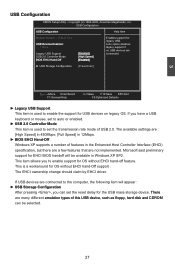
The available settings are : [High Speed] in 480Mbps; [Full Speed] in 12Mbps. ► BIOS EHCI Hand-Off Windows XP supports a number of USB 2.0. This item allows you to enable support for OS without EHCI hand-Off support . If USB ... T��h�e�r�e� are connected to set the reset delay for USB devices on legacy OS. Microsoft said preliminary support for EHCI BIOS handoff will appear : ► USB Storage Configuration After pressing , you have a USB keyboard or mouse, set to enable the support for the USB mass storage...
The available settings are : [High Speed] in 480Mbps; [Full Speed] in 12Mbps. ► BIOS EHCI Hand-Off Windows XP supports a number of USB 2.0. This item allows you to enable support for OS without EHCI hand-Off support . If USB ... T��h�e�r�e� are connected to set the reset delay for USB devices on legacy OS. Microsoft said preliminary support for EHCI BIOS handoff will appear : ► USB Storage Configuration After pressing , you have a USB keyboard or mouse, set to enable the support for the USB mass storage...
English manual.
Page 45
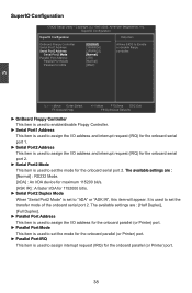
...;r�I�O��C�o��n�fi�g�u�r�a�t�io�n� Help Item OnBoard Floppy Controller [Enabled] Allows BIOS to Enable Serial Port1 Address [3F8/IRQ4] or disable floppy �S��e�ri�a�l�P��o�rt�2��...
...;r�I�O��C�o��n�fi�g�u�r�a�t�io�n� Help Item OnBoard Floppy Controller [Enabled] Allows BIOS to Enable Serial Port1 Address [3F8/IRQ4] or disable floppy �S��e�ri�a�l�P��o�rt�2��...
English manual.
Page 46
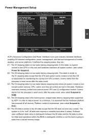
... is lost except system memory. In order to reduce power to distinguish whether or not the boot is responsible for initial boot operations within the BIOS to a minimum, it wakes. The S1 sleeping state is a low wake latency sleeping state. The S2 sleeping state is a low wake latency sleeping state. Hardware...
... is lost except system memory. In order to reduce power to distinguish whether or not the boot is responsible for initial boot operations within the BIOS to a minimum, it wakes. The S1 sleeping state is a low wake latency sleeping state. The S2 sleeping state is a low wake latency sleeping state. Hardware...


