
Fluke 8808A Digital Multimeter Datasheet
Page 8
... line fuse, statement of cal practices, WEEE information sheet, Warranty statement, Getting Started guide (English, French, German, Spanish, Italian, Simplified Chinese, Japanese), CD Rom with user manual (English). 8 Fluke Corporation Fluke 8808A Digital Multimeter Extended Specifications Fluke. Keeping your world up and running.® Fluke Corporation PO Box 9090, Everett, WA USA 98206...
... line fuse, statement of cal practices, WEEE information sheet, Warranty statement, Getting Started guide (English, French, German, Spanish, Italian, Simplified Chinese, Japanese), CD Rom with user manual (English). 8 Fluke Corporation Fluke 8808A Digital Multimeter Extended Specifications Fluke. Keeping your world up and running.® Fluke Corporation PO Box 9090, Everett, WA USA 98206...

User Manual
Page 1
All product names are trademarks of their respective companies. ® 8808A Digital Multimeter Users Manual July 2007 © 2007 Fluke Corporation, All rights reserved.
All product names are trademarks of their respective companies. ® 8808A Digital Multimeter Users Manual July 2007 © 2007 Fluke Corporation, All rights reserved.

User Manual
Page 4
8808A Users Manual Storing and Shipping the Meter 2-3 Power Considerations 2-3 Selecting the Line Voltage 2-4 Replacing the Fuses 2-4 Line-Power Fuse 2-4 Current-Input Fuses 2-5 Connecting to Line Power 2-7 Turning Power On 2-8 Adjusting the Bail 2-8 Installing the Meter into an Equipment Rack 2-8 Cleaning the Meter 2-9 Fluke 45 Emulation 2-9 Illuminating All Display Segments 2-10 3 Operating the Meter from...
8808A Users Manual Storing and Shipping the Meter 2-3 Power Considerations 2-3 Selecting the Line Voltage 2-4 Replacing the Fuses 2-4 Line-Power Fuse 2-4 Current-Input Fuses 2-5 Connecting to Line Power 2-7 Turning Power On 2-8 Adjusting the Bail 2-8 Installing the Meter into an Equipment Rack 2-8 Cleaning the Meter 2-9 Fluke 45 Emulation 2-9 Illuminating All Display Segments 2-10 3 Operating the Meter from...

User Manual
Page 12
8808A Users Manual 1-2
8808A Users Manual 1-2

User Manual
Page 13
1 Introduction and Specifications Introduction Introduction The Fluke 8808A Digital Multimeter (hereafter referred to determine if a measurement is a 5-1/2 digit dual-display multimeter designed for this Meter consists of 2.5, 20 and... 20 Hz to 1 MHz • Continuity and diode test • Measurement rates of a printed Getting Started Manual and a Users Manual on a CD-ROM. The Getting Started Manual contains basic getting started information, contacting Fluke, unpacking, and general specifications. 1-3 Some features provided by the Meter are: • A dual vacuum fluorescent display...
1 Introduction and Specifications Introduction Introduction The Fluke 8808A Digital Multimeter (hereafter referred to determine if a measurement is a 5-1/2 digit dual-display multimeter designed for this Meter consists of 2.5, 20 and... 20 Hz to 1 MHz • Continuity and diode test • Measurement rates of a printed Getting Started Manual and a Users Manual on a CD-ROM. The Getting Started Manual contains basic getting started information, contacting Fluke, unpacking, and general specifications. 1-3 Some features provided by the Meter are: • A dual vacuum fluorescent display...

User Manual
Page 14
... supplied in accordance with and around electricity. 1-4 In addition, follow all the safety instructions or warnings given throughout this Manual This manual contains all generally accepted safety practices and procedures required when working with the European standard publication EN61010-1: 2001 and U.S. ...before attempting to a power source, and turning the Meter on using the Meter to operate the Meter effectively. 8808A Users Manual About this manual that could result in a safe condition and ensure safe operation. To use the Meter, and standard and optional accessories ...
... supplied in accordance with and around electricity. 1-4 In addition, follow all the safety instructions or warnings given throughout this Manual This manual contains all generally accepted safety practices and procedures required when working with the European standard publication EN61010-1: 2001 and U.S. ...before attempting to a power source, and turning the Meter on using the Meter to operate the Meter effectively. 8808A Users Manual About this manual that could result in a safe condition and ensure safe operation. To use the Meter, and standard and optional accessories ...

User Manual
Page 16
...manual. AC (Alternating Current) DC (Direct Current) AC or DC (Alternating or Direct Current) Continuity test or continuity beeper tone Potentially hazardous voltage Double insulated Static awareness. Symbol P J E G I Y U < ~ CAT I is for measurements performed on the Meter or in this product as unsorted municipal waste. Contact Fluke...and Electrical Symbols Symbol W X B F D or C R Y T h CAT II Description Risk of this manual. 8808A Users Manual Symbols Table 1-2 lists safety and electrical symbols that appear on circuits directly connected to mains. 1-6 Static discharge can ...
...manual. AC (Alternating Current) DC (Direct Current) AC or DC (Alternating or Direct Current) Continuity test or continuity beeper tone Potentially hazardous voltage Double insulated Static awareness. Symbol P J E G I Y U < ~ CAT I is for measurements performed on the Meter or in this product as unsorted municipal waste. Contact Fluke...and Electrical Symbols Symbol W X B F D or C R Y T h CAT II Description Risk of this manual. 8808A Users Manual Symbols Table 1-2 lists safety and electrical symbols that appear on circuits directly connected to mains. 1-6 Static discharge can ...

User Manual
Page 18
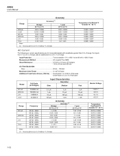
8808A Users Manual General Specifications Voltage 100V Setting 90 V to 110 V 120V Setting 108 V to 132 V 220V Setting 198 V to 242 V 240V Setting 216 V to 264 V Frequency 47 ...
8808A Users Manual General Specifications Voltage 100V Setting 90 V to 110 V 120V Setting 108 V to 132 V 220V Setting 198 V to 242 V 240V Setting 216 V to 264 V Frequency 47 ...

User Manual
Page 20
For inputs from 1 % to 5 % of range. 8808A Users Manual AC Voltage Specifications AC Voltage specifications are for ac sinewave signals >5 % of range and
For inputs from 1 % to 5 % of range. 8808A Users Manual AC Voltage Specifications AC Voltage specifications are for ac sinewave signals >5 % of range and
User Manual
Page 22
For inputs from 1 % to 5 % of range, add an additional error of 0.1 % of range. 8808A Users Manual Accuracy Accuracy [1] Range 90 days 23 °C ± 5 °C 200 μA 2 mA 20 mA 200 mA 2 A 10 A 0.02 + 0.005 0.015 + 0.005 0.03 + 0.02 0.02 + 0.005 0....
For inputs from 1 % to 5 % of range, add an additional error of 0.1 % of range. 8808A Users Manual Accuracy Accuracy [1] Range 90 days 23 °C ± 5 °C 200 μA 2 mA 20 mA 200 mA 2 A 10 A 0.02 + 0.005 0.015 + 0.005 0.03 + 0.02 0.02 + 0.005 0....

User Manual
Page 24
8808A Users Manual 1-14
8808A Users Manual 1-14

User Manual
Page 26
8808A Users Manual 2-2
8808A Users Manual 2-2

User Manual
Page 28
... it with the power supply. Line-Power Fuse The Meter has a line-power fuse in the line-fuse holder on four different input line voltages. 8808A Users Manual Selecting the Line Voltage The Meter operates on the Meter's rear panel. 1. Rotate the selector block until the holder pops out. Replacing the Fuses The...
... it with the power supply. Line-Power Fuse The Meter has a line-power fuse in the line-fuse holder on four different input line voltages. 8808A Users Manual Selecting the Line Voltage The Meter operates on the Meter's rear panel. 1. Rotate the selector block until the holder pops out. Replacing the Fuses The...
User Manual
Page 30
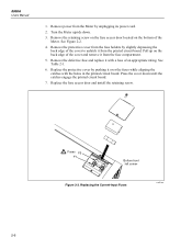
... screw on the fuse access door located on the back edge of an appropriate rating. Replace the fuse access door and install the retaining screw. 8808A Users Manual 1. Pull up on the bottom of the cover to unlatch it from the printed circuit board. Replacing the Current-Input Fuses eue04.eps 2-6 Replace the...
... screw on the fuse access door located on the back edge of an appropriate rating. Replace the fuse access door and install the retaining screw. 8808A Users Manual 1. Pull up on the bottom of the cover to unlatch it from the printed circuit board. Replacing the Current-Input Fuses eue04.eps 2-6 Replace the...
User Manual
Page 32
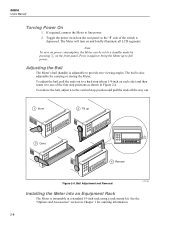
... pressing P on and briefly illuminate all the way out. 1 Store 2 Tilt up to provide two viewing angles. The Meter will turn on the front panel. 8808A Users Manual Turning Power On 1. Press it to bring the Meter up 3 Carry 4 Remove Figure 2-4. To remove the bail, adjust it again to the vertical stop positions...
... pressing P on and briefly illuminate all the way out. 1 Store 2 Tilt up to provide two viewing angles. The Meter will turn on the front panel. 8808A Users Manual Turning Power On 1. Press it to bring the Meter up 3 Carry 4 Remove Figure 2-4. To remove the bail, adjust it again to the vertical stop positions...

User Manual
Page 34
Press R to normal measurement mode, press S. 2-10 Release the buttons when the display illuminates. To return to set the mode and reset the Meter. The presently selected mode will appear bright in the display, while the other is dim. Next, press and hold Sthen press P to turn on the Meter. Illuminating All Display Segments To illimunate all display segments, start wth the Meter display off. 8808A Users Manual Press Uor Vto scroll between F8808A and F45.
Press R to normal measurement mode, press S. 2-10 Release the buttons when the display illuminates. To return to set the mode and reset the Meter. The presently selected mode will appear bright in the display, while the other is dim. Next, press and hold Sthen press P to turn on the Meter. Illuminating All Display Segments To illimunate all display segments, start wth the Meter display off. 8808A Users Manual Press Uor Vto scroll between F8808A and F45.

User Manual
Page 36
8808A Users Manual Calibration ...3-25 3-2
8808A Users Manual Calibration ...3-25 3-2

User Manual
Page 38
8808A Users Manual 1 2 3 4 2W/4W HI INPUT V SENSE 4W HI 1000V 750V MAX LO 200 mA MAX 1000 V 600 V CAT I CAT II 300 V 1V LO 500 Vpk 10 A MAX mA 10 A 8808A 5-1/2 DIGIT MULTIMETER 17 16 15 14 13 12 11 10 9 8 7 5 6 Figure 3-1. Front-Panel Features No. The LO input is isolated and may be...
8808A Users Manual 1 2 3 4 2W/4W HI INPUT V SENSE 4W HI 1000V 750V MAX LO 200 mA MAX 1000 V 600 V CAT I CAT II 300 V 1V LO 500 Vpk 10 A MAX mA 10 A 8808A 5-1/2 DIGIT MULTIMETER 17 16 15 14 13 12 11 10 9 8 7 5 6 Figure 3-1. Front-Panel Features No. The LO input is isolated and may be...

User Manual
Page 40
.... The annunciators indicate measurement units and the Meter's operating configuration. Function modifiers REL, HOLD, MIN MAX, and dB and the manual range mode cannot be selected for the input signal you to see the "How the Meter Takes Dual Display Measurements" section in ...lower segment of the dual display, and consists of a primary display and a secondary display, which show measurement readings, annunciators and messages. 8808A Users Manual Dual Display The Meter has a 5-1/2 digit vacuum fluorescent dual display. See Figure 3-2 and Table 32 for an overview of the display ...
.... The annunciators indicate measurement units and the Meter's operating configuration. Function modifiers REL, HOLD, MIN MAX, and dB and the manual range mode cannot be selected for the input signal you to see the "How the Meter Takes Dual Display Measurements" section in ...lower segment of the dual display, and consists of a primary display and a secondary display, which show measurement readings, annunciators and messages. 8808A Users Manual Dual Display The Meter has a 5-1/2 digit vacuum fluorescent dual display. See Figure 3-2 and Table 32 for an overview of the display ...

User Manual
Page 42
8808A Users Manual Rear Panel See Figure 3-3 and Table 3-3 for an overview of the rear-panel features. 1 2 3 220 5 4 Figure 3-3. Rear-Panel Features No. When manual ranging is selected, Manual Range is displayed. Name A Line power terminal B Power switch C Fuse holder and power line voltage selector D RS-232 terminal ... R to ground Adjusting Meter Range Ranging operations are performed using R, Uand V. Provides connection to toggle between autorange and manual range modes. Rear Panel eue03.eps Table 3-3. When autoranging is selected, Auto Range is displayed. 3-8
8808A Users Manual Rear Panel See Figure 3-3 and Table 3-3 for an overview of the rear-panel features. 1 2 3 220 5 4 Figure 3-3. Rear-Panel Features No. When manual ranging is selected, Manual Range is displayed. Name A Line power terminal B Power switch C Fuse holder and power line voltage selector D RS-232 terminal ... R to ground Adjusting Meter Range Ranging operations are performed using R, Uand V. Provides connection to toggle between autorange and manual range modes. Rear Panel eue03.eps Table 3-3. When autoranging is selected, Auto Range is displayed. 3-8


