Fluke 744 Users Manual
Page 13
...; BC7217 battery charger with Instruction Sheet • Adjustable quick-release strap (PN 946769) • Jumper for three-wire RTD measurement connections (two included, PN 944632) Documenting Process Calibrator Standard Equipment • 744 Users Manual English (PN 691287) French (PN 691300) German (PN 691311) Italian (PN 691318) Spanish (PN ...691303) • 744 HART® Mode Users Guide English (PN 691292) French (PN 691326) German (PN 691334) Italian (PN 691337) Spanish (PN 691329) &#...
...; BC7217 battery charger with Instruction Sheet • Adjustable quick-release strap (PN 946769) • Jumper for three-wire RTD measurement connections (two included, PN 944632) Documenting Process Calibrator Standard Equipment • 744 Users Manual English (PN 691287) French (PN 691300) German (PN 691311) Italian (PN 691318) Spanish (PN ...691303) • 744 HART® Mode Users Guide English (PN 691292) French (PN 691326) German (PN 691334) Italian (PN 691337) Spanish (PN 691329) &#...
Fluke 744 Users Manual
Page 22
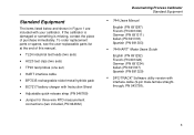
... to center. Jack for bench-top applications where ac line power is available. Use the battery eliminator for measuring or simulating thermocouples. or four-wire RTDs (Resistance Temperature Detectors). Input/Output Jacks and Connectors No. 1 2 3 4 5, 6 7, 8 9,10 Name Description Battery Eliminator jack w...spaced 7.9 mm (0.312 in) center to a pressure module. Input jacks for the Model BE9005 Battery Eliminator. Jacks for simulating RTDs. 12 Connects the calibrator to an RS-232 serial port on a personal computer. Output jacks for sourcing voltage, resistance, ...
... to center. Jack for bench-top applications where ac line power is available. Use the battery eliminator for measuring or simulating thermocouples. or four-wire RTDs (Resistance Temperature Detectors). Input/Output Jacks and Connectors No. 1 2 3 4 5, 6 7, 8 9,10 Name Description Battery Eliminator jack w...spaced 7.9 mm (0.312 in) center to a pressure module. Input jacks for the Model BE9005 Battery Eliminator. Jacks for simulating RTDs. 12 Connects the calibrator to an RS-232 serial port on a personal computer. Output jacks for sourcing voltage, resistance, ...

Fluke 744 Users Manual
Page 47
... -200 to 630 37 The calibrator accepts RTD measurement inputs in two-, three-, or four-wire connections as shown in a three-terminal configuration. A four-wire configuration provides the highest measurement precision, and two-wire provides the lowest measurement precision. The most common... R0 is called the "ice point" or R0. RTDs are characterized by their ...
... -200 to 630 37 The calibrator accepts RTD measurement inputs in two-, three-, or four-wire connections as shown in a three-terminal configuration. A four-wire configuration provides the highest measurement precision, and two-wire provides the lowest measurement precision. The most common... R0 is called the "ice point" or R0. RTDs are characterized by their ...

Fluke 744 Users Manual
Page 48
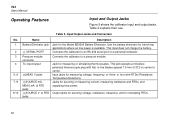
Press u or d to select a 2-, 3-, or 4- wire connection. 6. Caution Do not force a dual banana plug between the mA Ω RTD MEAS low jack and the V MEAS low jack as shown if you are using an RTD input, proceed as the display or Figure 15 shows. ...select the desired RTD type. 4. Attach the RTD to input jacks as follows: 1. Press e. See Figure 14. 38 744 Users Manual To measure temperature using a 3wire connection. 7. Use the supplied jumper wire when needed for MEASURE mode. 2. If necessary, press M for RTD measurements. Press t twice so that Select RTD Type shows....
Press u or d to select a 2-, 3-, or 4- wire connection. 6. Caution Do not force a dual banana plug between the mA Ω RTD MEAS low jack and the V MEAS low jack as shown if you are using an RTD input, proceed as the display or Figure 15 shows. ...select the desired RTD type. 4. Attach the RTD to input jacks as follows: 1. Press e. See Figure 14. 38 744 Users Manual To measure temperature using a 3wire connection. 7. Use the supplied jumper wire when needed for MEASURE mode. 2. If necessary, press M for RTD measurements. Press t twice so that Select RTD Type shows....
Fluke 744 Users Manual
Page 60
...middle column) jacks are dedicated to source loop power: 1. Note that the SOURCE mA, measure RTD, and measure Ω functions are two or fewer devices on the loop in order to operate correctly... Proceed as Figure 18 shows. Press e for two or three 4-20 mA devices on a typical 4- 744 Users Manual Supplying Loop Power The calibrator supplies loop power at 20 mA. Use the 24 V setting if...Connect the calibrator in addition to select Enabled 24 V or Enabled 28 V. 4. to the two-wire transmitter. (Each device on the loop in series with the instrument current loop as follows to sourcing ...
...middle column) jacks are dedicated to source loop power: 1. Note that the SOURCE mA, measure RTD, and measure Ω functions are two or fewer devices on the loop in order to operate correctly... Proceed as Figure 18 shows. Press e for two or three 4-20 mA devices on a typical 4- 744 Users Manual Supplying Loop Power The calibrator supplies loop power at 20 mA. Use the 24 V setting if...Connect the calibrator in addition to select Enabled 24 V or Enabled 28 V. 4. to the two-wire transmitter. (Each device on the loop in series with the instrument current loop as follows to sourcing ...
Fluke 744 Users Manual
Page 66
...wire transmitters, use the 4-inch long stackable jumper cables to simulate as prompted by the display, then press e. 56 The figure shows connections for SOURCE mode. 2. Proceed as follows to select the desired RTD type. 4. Press the u or d keys followed by the calibrator. Press t until the select RTD type display is showing. 3. 744... Users Manual Simulating RTDs Note Refer to the instrument under test as shown in...
...wire transmitters, use the 4-inch long stackable jumper cables to simulate as prompted by the display, then press e. 56 The figure shows connections for SOURCE mode. 2. Proceed as follows to select the desired RTD type. 4. Press the u or d keys followed by the calibrator. Press t until the select RTD type display is showing. 3. 744... Users Manual Simulating RTDs Note Refer to the instrument under test as shown in...

Fluke 744 Users Manual
Page 80
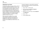
ENTER V mA RTD 30V MAX SOURCE 30V MAX mA RTD CAT MEAS 30V MAX V 300V MAX Red TC Miniplug TEST DC PWR - ++ +- Calibrating a Thermocouple Temperature Transmitter 70 ot23c.eps Supply + Black Figure 23. Original Circuit Wiring Power - 744 Users Manual 744 DOCUMENTING PROCESS CALIBRATOR Color depends on type of TC MEAS SOURCE mA SETUP V V Hz TC RTD 7 8 9 CLEAR ( ZERO) 4 5 6 1 2 3 0 .
ENTER V mA RTD 30V MAX SOURCE 30V MAX mA RTD CAT MEAS 30V MAX V 300V MAX Red TC Miniplug TEST DC PWR - ++ +- Calibrating a Thermocouple Temperature Transmitter 70 ot23c.eps Supply + Black Figure 23. Original Circuit Wiring Power - 744 Users Manual 744 DOCUMENTING PROCESS CALIBRATOR Color depends on type of TC MEAS SOURCE mA SETUP V V Hz TC RTD 7 8 9 CLEAR ( ZERO) 4 5 6 1 2 3 0 .

Fluke 744 Users Manual
Page 102
Original Circuit Wiring Power - 744 Users Manual 744 DOCUMENTING PROCESS CALIBRATOR Measure mA Loop Power Disabled MEAS SOURCE mA SETUP V V Hz TC RTD 7 8 9 CLEAR ( ZERO) 4 5 6 1 2 3 0 . ENTER V mA mA V RTD RTD CAT 30V MAX SOURCE 30V MEAS 30V 300V MAX TC MAX MAX Red TEST DC PWR - ++ +- Measuring the Output Current of a Transmitter 92 ot29c.eps Supply + Black Figure 29.
Original Circuit Wiring Power - 744 Users Manual 744 DOCUMENTING PROCESS CALIBRATOR Measure mA Loop Power Disabled MEAS SOURCE mA SETUP V V Hz TC RTD 7 8 9 CLEAR ( ZERO) 4 5 6 1 2 3 0 . ENTER V mA mA V RTD RTD CAT 30V MAX SOURCE 30V MEAS 30V 300V MAX TC MAX MAX Red TEST DC PWR - ++ +- Measuring the Output Current of a Transmitter 92 ot29c.eps Supply + Black Figure 29.

Fluke 744 Users Manual
Page 127
...;C Maximum Input Voltage: 30 V Maximum Input Current for RTD Source: 10 Ω RTDs: 8 mA dc; 100 Ω − 120 Ω RTDs: 8 mA dc; 200 Ω − 1000 Ω RTDs: 1 mA dc, supports pulsed transmitters and PLCs with pulse times as short as 1 ms For two and three-wire RTD measurements, add 0.4°C to the specifications. 117
...;C Maximum Input Voltage: 30 V Maximum Input Current for RTD Source: 10 Ω RTDs: 8 mA dc; 100 Ω − 120 Ω RTDs: 8 mA dc; 200 Ω − 1000 Ω RTDs: 1 mA dc, supports pulsed transmitters and PLCs with pulse times as short as 1 ms For two and three-wire RTD measurements, add 0.4°C to the specifications. 117
