Fluke 741B, 743B, and 744 Process Calibrator Datasheet
Page 1
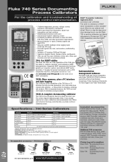
...; It handles fast pulsed instruments such as RTD transmitters and PLCs, with pulses as short as 1 ms. See www.fluke.com/744upgrade for plants that don't use the Fluke 744 to fill out calibration forms. Specifications - 740 Series Calibrators Function DC voltage DC current Resistance Frequency Thermocouples RTDs Pressure Measure Sourcing 0.025 % reading + 0.005...
...; It handles fast pulsed instruments such as RTD transmitters and PLCs, with pulses as short as 1 ms. See www.fluke.com/744upgrade for plants that don't use the Fluke 744 to fill out calibration forms. Specifications - 740 Series Calibrators Function DC voltage DC current Resistance Frequency Thermocouples RTDs Pressure Measure Sourcing 0.025 % reading + 0.005...

Fluke 744 Users Manual
Page 2
...Following repair, the product will be returned to the Buyer transportation prepaid and the Buyer will be free from defects in transit. Fluke Corporation P.O. THIS WARRANTY IS BUYER'S SOLE AND EXCLUSIVE REMEDY AND IS IN LIEU OF ALL OTHER WARRANTIES, EXPRESS OR IMPLIED,...period is three years and begins on behalf of shipment. To obtain warranty service, contact your nearest Fluke authorized service center or send the product, with its functional specifications for damage in material and workmanship under normal use and service. LIMITED WARRANTY & LIMITATION OF LIABILITY ...
...Following repair, the product will be returned to the Buyer transportation prepaid and the Buyer will be free from defects in transit. Fluke Corporation P.O. THIS WARRANTY IS BUYER'S SOLE AND EXCLUSIVE REMEDY AND IS IN LIEU OF ALL OTHER WARRANTIES, EXPRESS OR IMPLIED,...period is three years and begins on behalf of shipment. To obtain warranty service, contact your nearest Fluke authorized service center or send the product, with its functional specifications for damage in material and workmanship under normal use and service. LIMITED WARRANTY & LIMITATION OF LIABILITY ...
Fluke 744 Users Manual
Page 6
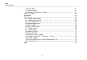
744 Users Manual Calibration Data ...99 In Case of Difficulty 99 Service Center Calibration or Repair 100 Replacement Parts ...101 Accessories...102 Specifications...104 DC Voltage Measurement 105 AC Voltage Measurement 106 DC Current Measurement 107 Resistance Measurement 107 Continuity Testing ...108 Frequency Measurement 108 DC Voltage Output ...... 112 Temperature, Thermocouples 113 Temperature, Resistance Temperature Detectors 116 Loop Power Supply 118 Top and Bottom Limits of Ranges with Auto Range On 119 General Specifications 121 Index ...125 iv
744 Users Manual Calibration Data ...99 In Case of Difficulty 99 Service Center Calibration or Repair 100 Replacement Parts ...101 Accessories...102 Specifications...104 DC Voltage Measurement 105 AC Voltage Measurement 106 DC Current Measurement 107 Resistance Measurement 107 Continuity Testing ...108 Frequency Measurement 108 DC Voltage Output ...... 112 Temperature, Thermocouples 113 Temperature, Resistance Temperature Detectors 116 Loop Power Supply 118 Top and Bottom Limits of Ranges with Auto Range On 119 General Specifications 121 Index ...125 iv
Fluke 744 Users Manual
Page 10
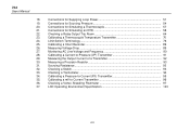
.... Connections for Supplying Loop Power 51 19. Calibrating a Pressure-to Current Transmitter 96 36. Calibrating a mV to -Current (P/I /P) Transmitter 91 29. LCD Operating Environment Specification 123 viii 744 Users Manual 18. Measuring Voltage Drop ...89 27. Calibrating a Current-to-Pressure (I ) Transmitter 95 35. Sourcing Resistance...93 32. Limit Switch Terminology...76 25...
.... Connections for Supplying Loop Power 51 19. Calibrating a Pressure-to Current Transmitter 96 36. Calibrating a mV to -Current (P/I /P) Transmitter 91 29. LCD Operating Environment Specification 123 viii 744 Users Manual 18. Measuring Voltage Drop ...89 27. Calibrating a Current-to-Pressure (I ) Transmitter 95 35. Sourcing Resistance...93 32. Limit Switch Terminology...76 25...
Fluke 744 Users Manual
Page 11
Refer to the 744 HART® Mode Users Guide for later review. 1 In addition to these functions, the calibrator has the following features: • General features: An analog display ... and internal isothermal block with HART-capable transmitters. Calibrator Specifications are at the back of the measuring and sourcing functions provided by the calibrator is shown in Table 1. The ability to store results for instructions on process instruments. Documenting Process Calibrator Introduction The Fluke 744 Documenting Process Calibrator (hereafter referred to as the...
Refer to the 744 HART® Mode Users Guide for later review. 1 In addition to these functions, the calibrator has the following features: • General features: An analog display ... and internal isothermal block with HART-capable transmitters. Calibrator Specifications are at the back of the measuring and sourcing functions provided by the calibrator is shown in Table 1. The ability to store results for instructions on process instruments. Documenting Process Calibrator Introduction The Fluke 744 Documenting Process Calibrator (hereafter referred to as the...
Fluke 744 Users Manual
Page 32
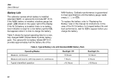
Table 4 shows the typical operating time for instructions. Calibrator performance is time to meet specifications until the battery gauge reads empty (Y or b). If the Ni-Cd battery is installed, there is no battery level indication except for a ...charged NiMH (Nickel-Metal Hydride) battery pack. Table 4. The optional Ni-Cd battery (Model BP7217) provides approximately half the battery life of the display. 744 Users Manual Battery Life The calibrator senses which battery is installed, a battery gauge bar graph Z shows on , continuous Typical intermittent operation 13 Hours 7 ...
Table 4 shows the typical operating time for instructions. Calibrator performance is time to meet specifications until the battery gauge reads empty (Y or b). If the Ni-Cd battery is installed, there is no battery level indication except for a ...charged NiMH (Nickel-Metal Hydride) battery pack. Table 4. The optional Ni-Cd battery (Model BP7217) provides approximately half the battery life of the display. 744 Users Manual Battery Life The calibrator senses which battery is installed, a battery gauge bar graph Z shows on , continuous Typical intermittent operation 13 Hours 7 ...
Fluke 744 Users Manual
Page 38
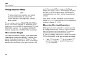
...function from either "Range" or "Auto Range" depending on the display. Measurement Ranges The calibrator normally changes to the appropriate measurement range automatically. 744 Users Manual Using Measure Mode Note To achieve best noise rejection and highest accuracy performance, do not use the battery eliminator, and tie all ...three common jacks together. If the calibrator is not in the specifications at the end of the display shows either SOURCE or MEASURE/SOURCE mode, first press M for resistance. 28
...function from either "Range" or "Auto Range" depending on the display. Measurement Ranges The calibrator normally changes to the appropriate measurement range automatically. 744 Users Manual Using Measure Mode Note To achieve best noise rejection and highest accuracy performance, do not use the battery eliminator, and tie all ...three common jacks together. If the calibrator is not in the specifications at the end of the display shows either SOURCE or MEASURE/SOURCE mode, first press M for resistance. 28
Fluke 744 Users Manual
Page 40
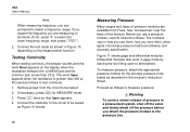
... word Open appears when the resistance is less than 400 Ω. Remove power from Fluke. Connect the test leads as shown in a pressurized system, shut off the valve and...a frequency range. To measure pressure, attach the appropriate pressure module for MEASURE mode. 3. 744 Users Manual Note When measuring frequency, you are prompted to test continuity: 1. Proceed as ... pressure: wWarning To avoid a violent release of process pressure media are allowed, and accuracy specification. Figure 11 shows gage and differential modules. If you expect the frequency you are available ...
... word Open appears when the resistance is less than 400 Ω. Remove power from Fluke. Connect the test leads as shown in a pressurized system, shut off the valve and...a frequency range. To measure pressure, attach the appropriate pressure module for MEASURE mode. 3. 744 Users Manual Note When measuring frequency, you are prompted to test continuity: 1. Proceed as ... pressure: wWarning To avoid a violent release of process pressure media are allowed, and accuracy specification. Figure 11 shows gage and differential modules. If you expect the frequency you are available ...
Fluke 744 Users Manual
Page 54
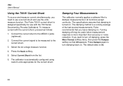
... using custom units appropriate for use the volts measure function. The calibrator is designed specifically for the current shunt. Connect the current shunt to dampen measurements in all functions except continuity. Fluke recommends that Off appears. The default state is turned on. Select the dc voltage... Turning damping off damping, press the More Choices softkey twice, then press the Dampen softkey so that you leave damping on . 744 Users Manual Using the 700-IV Current Shunt To source and measure current simultaneously, you need to use a current shunt and use...
... using custom units appropriate for use the volts measure function. The calibrator is designed specifically for the current shunt. Connect the current shunt to dampen measurements in all functions except continuity. Fluke recommends that Off appears. The default state is turned on. Select the dc voltage... Turning damping off damping, press the More Choices softkey twice, then press the Dampen softkey so that you leave damping on . 744 Users Manual Using the 700-IV Current Shunt To source and measure current simultaneously, you need to use a current shunt and use...
Fluke 744 Users Manual
Page 62
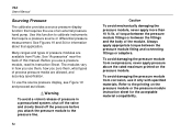
...module fitting and connecting fittings or adapters. To avoid damaging the pressure module from Fluke. See Figures 19 and 34 for the acceptable material compatibility. of the module.... pressure before you attach the pressure module to the printing on the pressure module. 744 Users Manual Sourcing Pressure The calibrator provides a source pressure display function that requires the...pressure hand pump. Many ranges and types of pressure modules are allowed, and accuracy specification. To avoid damaging the pressure module from overpressure, never apply pressure above the rated ...
...module fitting and connecting fittings or adapters. To avoid damaging the pressure module from Fluke. See Figures 19 and 34 for the acceptable material compatibility. of the module.... pressure before you attach the pressure module to the printing on the pressure module. 744 Users Manual Sourcing Pressure The calibrator provides a source pressure display function that requires the...pressure hand pump. Many ranges and types of pressure modules are allowed, and accuracy specification. To avoid damaging the pressure module from overpressure, never apply pressure above the rated ...

Fluke 744 Users Manual
Page 84
... is made for as the following. Now check the transmitter at step 3. If it is within specification, as left data. 74 If the span was taken. 4. When the tests are within specification, your adjustment is required. 6. 744 Users Manual 4. If not, adjust the linearity and begin an automatic sequence through the tests manually...
... is made for as the following. Now check the transmitter at step 3. If it is within specification, as left data. 74 If the span was taken. 4. When the tests are within specification, your adjustment is required. 6. 744 Users Manual 4. If not, adjust the linearity and begin an automatic sequence through the tests manually...

Fluke 744 Users Manual
Page 96
...gj55s.eps 86 Running a Preloaded Task Press the More Choices softkey until the Tasks softkey appear, then press Tasks to view the list of a specific transmitter. Press the c key to the normal display. Press the Min Max softkey again to revert to reset the Min Max registers. Clearing ...Memory In Setup mode, highlight the Clear Memory choice and press e to record and show the maximum and minimum readings. 744 Users Manual Recording Min and Max Measurements You can set the display to clear all the calibration parameters (source and measure functions, 0% and 100...
...gj55s.eps 86 Running a Preloaded Task Press the More Choices softkey until the Tasks softkey appear, then press Tasks to view the list of a specific transmitter. Press the c key to the normal display. Press the Min Max softkey again to revert to reset the Min Max registers. Clearing ...Memory In Setup mode, highlight the Clear Memory choice and press e to record and show the maximum and minimum readings. 744 Users Manual Recording Min and Max Measurements You can set the display to clear all the calibration parameters (source and measure functions, 0% and 100...

Fluke 744 Users Manual
Page 114
... valid only when Damping is displayed, floor specifications are the second part of the specifications, usually expressed as "% of Output" specifications by 3. Floor specifications, expressed as "% of full scale." 744 Users Manual • 80T-150U Temperature Probe • 80PK series thermocouples • 80i... the Y9108 adapter) • 80i-kW Current and Power Probe Specifications All specifications apply from +18 °C to +28 °C unless stated otherwise. The standard specification intervals for the 744 are specified only with damping on. Typical 90-day source and ...
... valid only when Damping is displayed, floor specifications are the second part of the specifications, usually expressed as "% of Output" specifications by 3. Floor specifications, expressed as "% of full scale." 744 Users Manual • 80T-150U Temperature Probe • 80PK series thermocouples • 80i... the Y9108 adapter) • 80i-kW Current and Power Probe Specifications All specifications apply from +18 °C to +28 °C unless stated otherwise. The standard specification intervals for the 744 are specified only with damping on. Typical 90-day source and ...

Fluke 744 Users Manual
Page 115
Documenting Process Calibrator Specifications DC Voltage Measurement Range Resolution % of Reading +% of Full Scale 1 Year 2 Year 110 mV 1 µV 0.025% + 0.015% 0.05% + 0.015% 1.1 V 10 µV 0.025% + 0.005% 0.05% + 0.005% ...
Documenting Process Calibrator Specifications DC Voltage Measurement Range Resolution % of Reading +% of Full Scale 1 Year 2 Year 110 mV 1 µV 0.025% + 0.015% 0.05% + 0.015% 1.1 V 10 µV 0.025% + 0.005% 0.05% + 0.005% ...
Fluke 744 Users Manual
Page 116
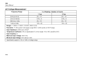
Input Impedance: 5 M Ω and 744 Users Manual AC Voltage Measurement Frequency Range % of Reading + Number of Counts 1 Year 2 Year 20 Hz to 40 Hz 2% + 10 2% + 10 40 Hz to 500 Hz 500 Hz to 1 kHz 0.5% + 5 2% + 10 0.5% + 5 2% + 10 1 kHz to 5 kHz 10% + 20 10% + 20 Ranges : 1.1000 V, 11.000 V, 110.00 V, 300.0 V rms Resolution: 11.000 counts in all ranges except 300 V; 3,000 counts on 300 V range.
Input Impedance: 5 M Ω and 744 Users Manual AC Voltage Measurement Frequency Range % of Reading + Number of Counts 1 Year 2 Year 20 Hz to 40 Hz 2% + 10 2% + 10 40 Hz to 500 Hz 500 Hz to 1 kHz 0.5% + 5 2% + 10 0.5% + 5 2% + 10 1 kHz to 5 kHz 10% + 20 10% + 20 Ranges : 1.1000 V, 11.000 V, 110.00 V, 300.0 V rms Resolution: 11.000 counts in all ranges except 300 V; 3,000 counts on 300 V range.

Fluke 744 Users Manual
Page 117
Documenting Process Calibrator Specifications DC Current Measurement Range Resolution 30 mA 110 mA 1 µA 10 µA % of Reading +% of Full Scale 1 Year 2 Year 0.01% + 0.015% 0.02% + 0.015% 0.01% + 0.015% 0....
Documenting Process Calibrator Specifications DC Current Measurement Range Resolution 30 mA 110 mA 1 µA 10 µA % of Reading +% of Full Scale 1 Year 2 Year 0.01% + 0.015% 0.02% + 0.015% 0.01% + 0.015% 0....

Fluke 744 Users Manual
Page 118
744 Users Manual Continuity Testing Tone Continuous tone May or may not get tone No tone Frequency Measurement Resistance 400 Ω Ranges 1.00 Hz to 109.99 Hz 110.0 Hz to 1099.9 Hz 1.100 kHz to 10.999 kHz 11.00 kHz to 50.00 kHz 1 Year 0.05 Hz 0.5 Hz 0.005 kHz 0.05 kHz Accuracy 2 Year 0.05 Hz 0.5 Hz 0.005 kHz 0.05 kHz Minimum Amplitude for Frequency Measurement (square wave): 30 kHz: 2.8 V p-p Maximum input: 1 kHz: 30 V rms Input Impedance: 5 MΩ For frequency measurement less than 109.99 Hz, specifications apply for signals with a slew rate greater than 5 volt/millisecond. 108
744 Users Manual Continuity Testing Tone Continuous tone May or may not get tone No tone Frequency Measurement Resistance 400 Ω Ranges 1.00 Hz to 109.99 Hz 110.0 Hz to 1099.9 Hz 1.100 kHz to 10.999 kHz 11.00 kHz to 50.00 kHz 1 Year 0.05 Hz 0.5 Hz 0.005 kHz 0.05 kHz Accuracy 2 Year 0.05 Hz 0.5 Hz 0.005 kHz 0.05 kHz Minimum Amplitude for Frequency Measurement (square wave): 30 kHz: 2.8 V p-p Maximum input: 1 kHz: 30 V rms Input Impedance: 5 MΩ For frequency measurement less than 109.99 Hz, specifications apply for signals with a slew rate greater than 5 volt/millisecond. 108

Fluke 744 Users Manual
Page 119
Documenting Process Calibrator Specifications DC Voltage Output Range Resolution % of Output + % of Full Scale 1 Year 2 Year 110 mV 1 µV 0.01% + 0.005% 0.015% + 0.005% 1.1 V 10 µV 0.01% + 0.005% 0.015% + 0.005% 15 V 100 µV 0.01% + 0.005% 0.015% + 0.005% Temperature Coefficient: (0.001% of output + 0.001% of f.s.)/°C in the ranges -10 to 18 °C and 28 to 50 °C Maximum Output Current: 10 mA Loading: (0.001% f.s. + 1 µV)/ mA Common Mode Error: 0.008% f.s/(Common Mode Volt) Maximum Input Voltage: 30 V dc 109
Documenting Process Calibrator Specifications DC Voltage Output Range Resolution % of Output + % of Full Scale 1 Year 2 Year 110 mV 1 µV 0.01% + 0.005% 0.015% + 0.005% 1.1 V 10 µV 0.01% + 0.005% 0.015% + 0.005% 15 V 100 µV 0.01% + 0.005% 0.015% + 0.005% Temperature Coefficient: (0.001% of output + 0.001% of f.s.)/°C in the ranges -10 to 18 °C and 28 to 50 °C Maximum Output Current: 10 mA Loading: (0.001% f.s. + 1 µV)/ mA Common Mode Error: 0.008% f.s/(Common Mode Volt) Maximum Input Voltage: 30 V dc 109

Fluke 744 Users Manual
Page 120
744 Users Manual DC Current Output Range/Mode Resolution % of Output + % of Full Scale 1 Year 2 Year 22 mA/ Source mA 1 µA 0.01% + 0.015% 0.02% + 0.015% 22 ... f.s.)/°C in the ranges -10 to 18°C and 28 to 50°C Common Mode Error: 0.008% f.s/(Common Mode Volt) Maximum Input Voltage: 30 V dc Specification applies for currents between 2 mA and 22 mA.
744 Users Manual DC Current Output Range/Mode Resolution % of Output + % of Full Scale 1 Year 2 Year 22 mA/ Source mA 1 µA 0.01% + 0.015% 0.02% + 0.015% 22 ... f.s.)/°C in the ranges -10 to 18°C and 28 to 50°C Common Mode Error: 0.008% f.s/(Common Mode Volt) Maximum Input Voltage: 30 V dc Specification applies for currents between 2 mA and 22 mA.

Fluke 744 Users Manual
Page 121
Documenting Process Calibrator Specifications Resistance Sourcing Range Resolution % of Output + ohms 1 Year 2 Year 11.000 Ω 1 mΩ 0.01% + 0.02 0.02% + 0.02 110.00 Ω 1.1000 kΩ 11.000 kΩ ...
Documenting Process Calibrator Specifications Resistance Sourcing Range Resolution % of Output + ohms 1 Year 2 Year 11.000 Ω 1 mΩ 0.01% + 0.02 0.02% + 0.02 110.00 Ω 1.1000 kΩ 11.000 kΩ ...
