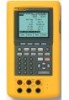
Fluke 741B, 743B, and 744 Process Calibrator Datasheet
Page 1
... all of the capabilities of the 743B, plus a PC interface that lets you calibrate and when? Ordering information Fluke-741B Documenting Process Calibrator Fluke-743B Documenting Process Calibrator Fluke-744 Documenting Process Calibrator For more information, go to monitor, control, and calibrate HART instrumentation. or unload data for calibration of HART smart transmitters is often misunderstood. When you to www.MyFlukeStore.com Additional...
... all of the capabilities of the 743B, plus a PC interface that lets you calibrate and when? Ordering information Fluke-741B Documenting Process Calibrator Fluke-743B Documenting Process Calibrator Fluke-744 Documenting Process Calibrator For more information, go to monitor, control, and calibrate HART instrumentation. or unload data for calibration of HART smart transmitters is often misunderstood. When you to www.MyFlukeStore.com Additional...

Fluke 744 Users Manual
Page 1
Users Manual Printed in U.S.A. All product names are trademarks of their respective companies. All rights reserved. ® 744 Documenting Process Calibrator PN 691287 September 1998 Rev.1, 2/99 © 1998,1999 Fluke Corporation.
Users Manual Printed in U.S.A. All product names are trademarks of their respective companies. All rights reserved. ® 744 Documenting Process Calibrator PN 691287 September 1998 Rev.1, 2/99 © 1998,1999 Fluke Corporation.
Fluke 744 Users Manual
Page 11
... how to use the HART communication feature. Refer to the 744 HART® Mode Users Guide for later review. 1 A thermocouple (TC) input/output jack and internal isothermal block with HART-capable transmitters. Documenting Process Calibrator Introduction The Fluke 744 Documenting Process Calibrator (hereafter referred to as the calibrator) is unstable. The ability to store results for instructions on...
... how to use the HART communication feature. Refer to the 744 HART® Mode Users Guide for later review. 1 A thermocouple (TC) input/output jack and internal isothermal block with HART-capable transmitters. Documenting Process Calibrator Introduction The Fluke 744 Documenting Process Calibrator (hereafter referred to as the calibrator) is unstable. The ability to store results for instructions on...
Fluke 744 Users Manual
Page 13
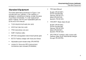
... quick-release strap (PN 946769) • Jumper for three-wire RTD measurement connections (two included, PN 944632) Documenting Process Calibrator Standard Equipment • 744 Users Manual English (PN 691287) French (PN 691300) German (PN 691311) Italian (PN 691318) Spanish (PN 691303) •...; 744 HART® Mode Users Guide English (PN 691292) French (PN 691326) German (PN 691334) Italian (PN 691337) Spanish (PN 691329) • DPC/TRACK™ Software utility version with your calibrator. Standard Equipment The items listed below and shown in...
... quick-release strap (PN 946769) • Jumper for three-wire RTD measurement connections (two included, PN 944632) Documenting Process Calibrator Standard Equipment • 744 Users Manual English (PN 691287) French (PN 691300) German (PN 691311) Italian (PN 691318) Spanish (PN 691303) •...; 744 HART® Mode Users Guide English (PN 691292) French (PN 691326) German (PN 691334) Italian (PN 691337) Spanish (PN 691329) • DPC/TRACK™ Software utility version with your calibrator. Standard Equipment The items listed below and shown in...
Fluke 744 Users Manual
Page 15
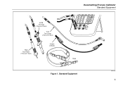
Standard Equipment ot01f.eps 5 AC20 Test Clip (2 Red and 2 Black) TL24 Test Leads (2 Red and 2 Black) TP20 Test Probe (1 Red and 1 Black) Jumper (2 Black) Documenting Process Calibrator Standard Equipment V 7 4 V Hz 8 9 5 6 TC RTD CLEAR ( ZERO) 1 2 3 0 . ENTER V RTD mA mA V RTD SOURCE 30V MAX MEAS 300V MAX TC Strap Figure 1.
Standard Equipment ot01f.eps 5 AC20 Test Clip (2 Red and 2 Black) TL24 Test Leads (2 Red and 2 Black) TP20 Test Probe (1 Red and 1 Black) Jumper (2 Black) Documenting Process Calibrator Standard Equipment V 7 4 V Hz 8 9 5 6 TC RTD CLEAR ( ZERO) 1 2 3 0 . ENTER V RTD mA mA V RTD SOURCE 30V MAX MEAS 300V MAX TC Strap Figure 1.
Fluke 744 Users Manual
Page 17
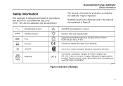
... (Installation) Category II, Pollution Degree 2 per IEC 1010-1 refers to relevent European Union directives. Use the calibrator only as specified in this manual are explained in manual Common (LO) Input equipotentiality Equipment protected throughout by the...with IEC1010-1 and CAN/CSA C22.2 No. 1010.1-92. Definition of Impluse Withstand Voltage protection provided. Documenting Process Calibrator Safety Information Safety Information This calibrator is designed and tested in this manual, otherwise the protection provided by DOUBLE INSULATION or REINFORCED INSULATION Conforms to ...
... (Installation) Category II, Pollution Degree 2 per IEC 1010-1 refers to relevent European Union directives. Use the calibrator only as specified in this manual are explained in manual Common (LO) Input equipotentiality Equipment protected throughout by the...with IEC1010-1 and CAN/CSA C22.2 No. 1010.1-92. Definition of Impluse Withstand Voltage protection provided. Documenting Process Calibrator Safety Information Safety Information This calibrator is designed and tested in this manual, otherwise the protection provided by DOUBLE INSULATION or REINFORCED INSULATION Conforms to ...
Fluke 744 Users Manual
Page 19
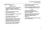
...damage to another measure or source function. Documenting Process Calibrator Safety Information • When servicing the calibrator, use only specified replacement parts. • Do not use any part of the case or cover removed. • Do not operate the calibrator around explosive gas, vapor, or dust. &#... Fluke model BE9005 Battery Eliminator. Safety Information (cont) Warning (cont) • Do not apply more than the rated voltage, as marked on the calibrator, between the terminals, or between any terminal and earth ground. • When using a pressure module, make sure the process ...
...damage to another measure or source function. Documenting Process Calibrator Safety Information • When servicing the calibrator, use only specified replacement parts. • Do not use any part of the case or cover removed. • Do not operate the calibrator around explosive gas, vapor, or dust. &#... Fluke model BE9005 Battery Eliminator. Safety Information (cont) Warning (cont) • Do not apply more than the rated voltage, as marked on the calibrator, between the terminals, or between any terminal and earth ground. • When using a pressure module, make sure the process ...

Fluke 744 Users Manual
Page 21
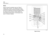
Jumper Connections for Demonstration Documenting Process Calibrator Getting Started Exercise Figure 4. TC RTD CLEAR ( ZERO) ENTER V mA mA V RTD RTD CAT 30V MAX SOURCE 30V MEAS 30V 300V MAX TC MAX MAX ot03f.eps Figure 3. Measure/Source Example gj4s.eps 11 V V Hz 7 8 9 4 5 6 1 2 3 0 .
Jumper Connections for Demonstration Documenting Process Calibrator Getting Started Exercise Figure 4. TC RTD CLEAR ( ZERO) ENTER V mA mA V RTD RTD CAT 30V MAX SOURCE 30V MEAS 30V 300V MAX TC MAX MAX ot03f.eps Figure 3. Measure/Source Example gj4s.eps 11 V V Hz 7 8 9 4 5 6 1 2 3 0 .

Fluke 744 Users Manual
Page 23
Input/Output Jacks and Connectors ot05f.eps 13 Documenting Process Calibrator Operating Features 744 DOCUMENTING PROCESS CALIBRATOR MEAS SOURCE V V Hz 7 8 9 4 5 6 1 2 3 0 . mA SETUP TC RTD CLEAR ( ZERO) ENTER V RTD mA mA V RTD CAT 30V MAX SOURCE 30V MEAS 30V 300V MAX TC MAX MAX 1 2 3 4 10 5 987 6 Figure 5.
Input/Output Jacks and Connectors ot05f.eps 13 Documenting Process Calibrator Operating Features 744 DOCUMENTING PROCESS CALIBRATOR MEAS SOURCE V V Hz 7 8 9 4 5 6 1 2 3 0 . mA SETUP TC RTD CLEAR ( ZERO) ENTER V RTD mA mA V RTD CAT 30V MAX SOURCE 30V MEAS 30V 300V MAX TC MAX MAX 1 2 3 4 10 5 987 6 Figure 5.
Fluke 744 Users Manual
Page 24
... unmarked blue keys just below the display. Softkey labels and other display text are shown in this manual in bold type, for example, Choices. 14 744 DOCUMENTING PROCESS CALIBRATOR 16 15 14 13 123 MEAS SOURCE mA SETUP V V Hz TC RTD 7 8 9 CLEAR ( ZERO) 4 5 6 1 2 3 0 . Keys 4 5 6 7 8 9 10 11 ot06f.eps ENTER V mA mA V RTD RTD...
... unmarked blue keys just below the display. Softkey labels and other display text are shown in this manual in bold type, for example, Choices. 14 744 DOCUMENTING PROCESS CALIBRATOR 16 15 14 13 123 MEAS SOURCE mA SETUP V V Hz TC RTD 7 8 9 CLEAR ( ZERO) 4 5 6 1 2 3 0 . Keys 4 5 6 7 8 9 10 11 ot06f.eps ENTER V mA mA V RTD RTD...
Fluke 744 Users Manual
Page 25
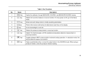
... Functions No. Name Description 1 M key Cycles the calibrator through MEASURE, SOURCE, and MEASURE/SOURCE modes. 2 m key Selects mA (current) measure or source function. In calculator mode, this key provides the square root function. 9 c key Clears a partial data entry, or zeros the output when in the SOURCE mode. Documenting Process Calibrator Operating Features Table 3.
... Functions No. Name Description 1 M key Cycles the calibrator through MEASURE, SOURCE, and MEASURE/SOURCE modes. 2 m key Selects mA (current) measure or source function. In calculator mode, this key provides the square root function. 9 c key Clears a partial data entry, or zeros the output when in the SOURCE mode. Documenting Process Calibrator Operating Features Table 3.
Fluke 744 Users Manual
Page 27
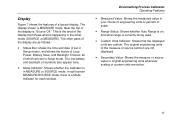
..., Battery Save, and Backlight Timeout; In split screen MEASURE/SOURCE mode, there is MEASURE mode. all of which are active. 17 Documenting Process Calibrator Operating Features • Measured Value: Shows the measured value in Setup mode), and shows the status of scale. • Range Status: ...Shows whether Auto Range is on symbols also appear here. • Mode Indicator: Shows whether the calibrator is in Setup mode. The other mode (SOURCE or MEASURE). Near the top of a typical display. Display Figure 7 shows the features of ...
..., Battery Save, and Backlight Timeout; In split screen MEASURE/SOURCE mode, there is MEASURE mode. all of which are active. 17 Documenting Process Calibrator Operating Features • Measured Value: Shows the measured value in Setup mode), and shows the status of scale. • Range Status: ...Shows whether Auto Range is on symbols also appear here. • Mode Indicator: Shows whether the calibrator is in Setup mode. The other mode (SOURCE or MEASURE). Near the top of a typical display. Display Figure 7 shows the features of ...
Fluke 744 Users Manual
Page 29
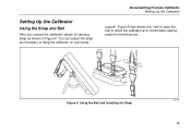
Using the Bail and Installing the Strap gj8f.eps 19 Setting Up the Calibrator Using the Strap and Bail After you how to open the bail to hang the calibrator on any sturdy Documenting Process Calibrator Setting Up the Calibrator support. Figure 8 also shows you unpack the calibrator, attach its carrying strap as necessary to stand the calibrator at a comfortable viewing angle for benchtop use. Figure 8. You can adjust the strap as shown in Figure 8.
Using the Bail and Installing the Strap gj8f.eps 19 Setting Up the Calibrator Using the Strap and Bail After you how to open the bail to hang the calibrator on any sturdy Documenting Process Calibrator Setting Up the Calibrator support. Figure 8 also shows you unpack the calibrator, attach its carrying strap as necessary to stand the calibrator at a comfortable viewing angle for benchtop use. Figure 8. You can adjust the strap as shown in Figure 8.
Fluke 744 Users Manual
Page 31
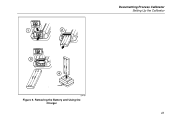
BATTERY ACCESS 1 BATTERY ACCESS BATTERY ACCESS 3 2 4 gj9f.eps Figure 9. Removing the Battery and Using the Charger Documenting Process Calibrator Setting Up the Calibrator 21
BATTERY ACCESS 1 BATTERY ACCESS BATTERY ACCESS 3 2 4 gj9f.eps Figure 9. Removing the Battery and Using the Charger Documenting Process Calibrator Setting Up the Calibrator 21
Fluke 744 Users Manual
Page 33
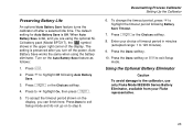
To accept the timeout period shown on the display, you are using the battery eliminator. Documenting Process Calibrator Setting Up the Calibrator 6. Press eor the Choices softkey. 8. Press e or the Choices softkey. 4. Press the Done softkey. 10. Press to step 6. Press... Eliminator Caution To avoid damage to highlight Off following Battery Save Timeout. 7. Turn on to u highlight On, then press e. 5. Enter your Fluke representative. 23 To change the timeout period, press d to 120 minutes). 9. Auto Battery Save works the same when using the optional NiCd battery...
To accept the timeout period shown on the display, you are using the battery eliminator. Documenting Process Calibrator Setting Up the Calibrator 6. Press eor the Choices softkey. 8. Press e or the Choices softkey. 4. Press the Done softkey. 10. Press to step 6. Press... Eliminator Caution To avoid damage to highlight Off following Battery Save Timeout. 7. Turn on to u highlight On, then press e. 5. Enter your Fluke representative. 23 To change the timeout period, press d to 120 minutes). 9. Auto Battery Save works the same when using the optional NiCd battery...
Fluke 744 Users Manual
Page 35
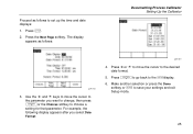
Proceed as follows: Documenting Process Calibrator Setting Up the Calibrator gj38s.eps 3. Press uor d to move the cursor to choose a setting for that parameter. Make another selection or press the Done softkey or s to the ...
Proceed as follows: Documenting Process Calibrator Setting Up the Calibrator gj38s.eps 3. Press uor d to move the cursor to choose a setting for that parameter. Make another selection or press the Done softkey or s to the ...

Fluke 744 Users Manual
Page 37
gj40s.eps 5. To erase a character, press the Back Space softkey. To erase the whole string, press c. 6. Press u, d, L, or R to exit Setup mode. Press the Done softkey. 9. Repeat step 6 until you want to enter a number. 7. Press eor the Choices softkey. The display appears as follows: Documenting Process Calibrator Setting Up the Calibrator 8. Press the Done softkey or s to select a character, then press e. Use the numeric keypad if you are satisfied with the ID string appearing in the window. 27 The ID string is shown at the bottom of the boxed area. 4.
gj40s.eps 5. To erase a character, press the Back Space softkey. To erase the whole string, press c. 6. Press u, d, L, or R to exit Setup mode. Press the Done softkey. 9. Repeat step 6 until you want to enter a number. 7. Press eor the Choices softkey. The display appears as follows: Documenting Process Calibrator Setting Up the Calibrator 8. Press the Done softkey or s to select a character, then press e. Use the numeric keypad if you are satisfied with the ID string appearing in the window. 27 The ID string is shown at the bottom of the boxed area. 4.
Fluke 744 Users Manual
Page 39
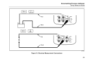
Electrical Measurement Connections gj10f.eps 29 Red Black Documenting Process Calibrator Using Measure Mode V mA mA V RTD RTD CAT 30V MAX SOURCE 30V MEAS 30V 300V MAX TC MAX MAX Red Black V mA mA V RTD RTD CAT 30V MAX SOURCE 30V MEAS 30V 300V MAX TC MAX MAX Figure 10. + -
Electrical Measurement Connections gj10f.eps 29 Red Black Documenting Process Calibrator Using Measure Mode V mA mA V RTD RTD CAT 30V MAX SOURCE 30V MEAS 30V 300V MAX TC MAX MAX Red Black V mA mA V RTD RTD CAT 30V MAX SOURCE 30V MEAS 30V 300V MAX TC MAX MAX Figure 10. + -
Fluke 744 Users Manual
Page 41
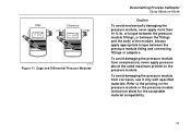
Gage and Differential Pressure Modules Documenting Process Calibrator Using Measure Mode Caution To avoid mechanically damaging the pressure module, never apply more than 10 ft.-lb. To avoid damaging the pressure module from ...
Gage and Differential Pressure Modules Documenting Process Calibrator Using Measure Mode Caution To avoid mechanically damaging the pressure module, never apply more than 10 ft.-lb. To avoid damaging the pressure module from ...
Fluke 744 Users Manual
Page 43
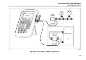
Connections for Measuring Pressure ot12c.eps 33 744 DOCUMENTING PROCESS CALIBRATOR MEAS SOURCE V V Hz 7 8 9 4 5 6 1 2 3 0 . mA SETUP TC RTD CLEAR ( ZERO) ENTER V RTD mA mA V RTD CAT 30V MAX SOURCE 30V MEAS 30V 300V MAX TC MAX MAX Documenting Process Calibrator Using Measure Mode Gage Module Isolation Valve Differential Module L H Tank Figure 12.
Connections for Measuring Pressure ot12c.eps 33 744 DOCUMENTING PROCESS CALIBRATOR MEAS SOURCE V V Hz 7 8 9 4 5 6 1 2 3 0 . mA SETUP TC RTD CLEAR ( ZERO) ENTER V RTD mA mA V RTD CAT 30V MAX SOURCE 30V MEAS 30V 300V MAX TC MAX MAX Documenting Process Calibrator Using Measure Mode Gage Module Isolation Valve Differential Module L H Tank Figure 12.


