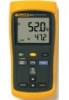
FE 51 & 52 II Users Manual
Page 3
Table of Contents Title Page Introduction ...1 Contacting Fluke ...1 Getting Started...4 Components...5 Display Elements ...6 Buttons...7 Using the Thermometer 9 Changing Setup Options 9 Entering or Exiting Setup 9 Setup Options ...9 Changing a Setup Option 10 Measuring Temperatures 11 Connecting a Thermocouple 11 Displaying Temperatures 11 Holding the Displayed Readings 12 Viewing the MIN, MAX, and AVG Readings 12 Using the Offset to Adjust for Probe Errors 12 i
Table of Contents Title Page Introduction ...1 Contacting Fluke ...1 Getting Started...4 Components...5 Display Elements ...6 Buttons...7 Using the Thermometer 9 Changing Setup Options 9 Entering or Exiting Setup 9 Setup Options ...9 Changing a Setup Option 10 Measuring Temperatures 11 Connecting a Thermocouple 11 Displaying Temperatures 11 Holding the Displayed Readings 12 Viewing the MIN, MAX, and AVG Readings 12 Using the Offset to Adjust for Probe Errors 12 i
FE 51 & 52 II Users Manual
Page 15
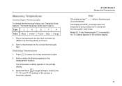
...T1, T2, and T1-T2 readings in the primary or secondary display. 51 & 52 Series II Measuring Temperatures Notes The display shows "- - - -" when a thermocouple is correct.) 2. T 3. Model 52: Press to select the correct temperature scale. 2. The North American ANSI Color Code... is outside the thermocouple's valid range. The temperature reading appears in the primary display. 11 The display shows 0L (overload) when the temperature being ...
...T1, T2, and T1-T2 readings in the primary or secondary display. 51 & 52 Series II Measuring Temperatures Notes The display shows "- - - -" when a thermocouple is correct.) 2. T 3. Model 52: Press to select the correct temperature scale. 2. The North American ANSI Color Code... is outside the thermocouple's valid range. The temperature reading appears in the primary display. 11 The display shows 0L (overload) when the temperature being ...