FE 192,196,199 C Users Manual
Page 7
... 83 Storing the Test Tool...83 Charging the Batteries 84 Extending Battery Operation Time 85 Replacing the NiMH Battery Pack BP190 86 Calibrating the Voltage Probes 86 Displaying Calibration Information 88 iii
... 83 Storing the Test Tool...83 Charging the Batteries 84 Extending Battery Operation Time 85 Replacing the NiMH Battery Pack BP190 86 Calibrating the Voltage Probes 86 Displaying Calibration Information 88 iii
FE 192,196,199 C Users Manual
Page 8
Fluke 192B - 196B/C - 199B/C Users Manual Parts and Accessories 88 Troubleshooting ...93 9 Specifications ...95 Introduction ...95 Dual Input Oscilloscope 96 Automatic Scope Measurements 98 Meter ...102 DMM Measurements on Meter Inputs 102 Recorder ...104 Zoom, Replay and Cursors 105 Miscellaneous ...105 Environmental...107 Safety ...107 10:1 Probe ...109 Electromagnetic Immunity 110 iv
Fluke 192B - 196B/C - 199B/C Users Manual Parts and Accessories 88 Troubleshooting ...93 9 Specifications ...95 Introduction ...95 Dual Input Oscilloscope 96 Automatic Scope Measurements 98 Meter ...102 DMM Measurements on Meter Inputs 102 Recorder ...104 Zoom, Replay and Cursors 105 Miscellaneous ...105 Environmental...107 Safety ...107 10:1 Probe ...109 Electromagnetic Immunity 110 iv
FE 192,196,199 C Users Manual
Page 11
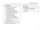
...with Hook Clip (red) d) Ground Lead with Mini Alligator Clip (black) e) 4-mm Test Probe for Probe Tip (red) f) Ground Spring for Probe Tip (black) 4 10:1 Voltage Probe Set (gray) a) 10:1 Voltage Probe (gray) b) Hook Clip for Probe Tip (gray) c) Ground Lead with Hook Clip (gray) d) Ground Lead with Mini Alligator... Clip (black) e) 4-mm Test Probe for Probe Tip (gray) 5 a) Test Lead Set b) Probe ground lead with 4 mm banana jack 6 Getting Started Manual 7 CD ROM with Users Manual (multi-language) 8 Shipment box (basic version only) Unpacking the Test Tool Kit Fluke 192B, 196B/C and 199B/C S ...
...with Hook Clip (red) d) Ground Lead with Mini Alligator Clip (black) e) 4-mm Test Probe for Probe Tip (red) f) Ground Spring for Probe Tip (black) 4 10:1 Voltage Probe Set (gray) a) 10:1 Voltage Probe (gray) b) Hook Clip for Probe Tip (gray) c) Ground Lead with Hook Clip (gray) d) Ground Lead with Mini Alligator... Clip (black) e) 4-mm Test Probe for Probe Tip (gray) 5 a) Test Lead Set b) Probe ground lead with 4 mm banana jack 6 Getting Started Manual 7 CD ROM with Users Manual (multi-language) 8 Shipment box (basic version only) Unpacking the Test Tool Kit Fluke 192B, 196B/C and 199B/C S ...

FE 192,196,199 C Users Manual
Page 13
...the instrument. Do not apply voltages that differ more than 4800 VA: • Use only insulated voltage probes, test leads and adapters supplied with the test tool, or indicated by Fluke as suitable for the Fluke190 ScopeMeter series. • Before use the test tool only in a CAT ...than 1000 V from each other to distribution level and fixed installation circuits inside a building. Use caution when using 1:1 test leads because the probe tip voltage will be directly transmitted to any input when measuring in a CAT II environment. Voltage ratings that differ more than 600 V from...
...the instrument. Do not apply voltages that differ more than 4800 VA: • Use only insulated voltage probes, test leads and adapters supplied with the test tool, or indicated by Fluke as suitable for the Fluke190 ScopeMeter series. • Before use the test tool only in a CAT ...than 1000 V from each other to distribution level and fixed installation circuits inside a building. Use caution when using 1:1 test leads because the probe tip voltage will be directly transmitted to any input when measuring in a CAT II environment. Voltage ratings that differ more than 600 V from...
FE 192,196,199 C Users Manual
Page 19
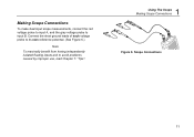
Making Scope Connections To make dual input scope measurements, connect the red voltage probe to input A, and the gray voltage probe to avoid problems caused by improper use, read Chapter 7: "Tips". 1 Using The Scope Making Scope Connections Figure 6. Scope Connections 11 Connect the short ground leads of each voltage probe to its own reference potential. (See Figure 6.) Note To maximally benefit from having independently isolated floating inputs and to input B.
Making Scope Connections To make dual input scope measurements, connect the red voltage probe to input A, and the gray voltage probe to avoid problems caused by improper use, read Chapter 7: "Tips". 1 Using The Scope Making Scope Connections Figure 6. Scope Connections 11 Connect the short ground leads of each voltage probe to its own reference potential. (See Figure 6.) Note To maximally benefit from having independently isolated floating inputs and to input B.
FE 192,196,199 C Users Manual
Page 37
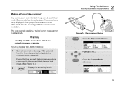
... To set up the test tool, do the following: 1 Connect a current probe (e.g. Ensure that the red and black probe connectors 5 correspond to be measured. Warning 3 Carefully read the instructions about the current probe you perform measurements. Highlight A ac.... The next example explains a typical current ...measurement in both Scope mode and Meter mode. Open the Current Probe submenu. 29 Meter mode has the advantage of two waveforms being displayed while you are using. i400, optional) from the ...
... To set up the test tool, do the following: 1 Connect a current probe (e.g. Ensure that the red and black probe connectors 5 correspond to be measured. Warning 3 Carefully read the instructions about the current probe you perform measurements. Highlight A ac.... The next example explains a typical current ...measurement in both Scope mode and Meter mode. Open the Current Probe submenu. 29 Meter mode has the advantage of two waveforms being displayed while you are using. i400, optional) from the ...
FE 192,196,199 C Users Manual
Page 38
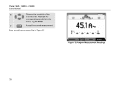
Ampere Measurement Readings 30 Highlight the corresponding sensitivity in Figure 15 Figure 15. Fluke 192B - 196B/C - 199B/C Users Manual 6 Observe the sensitivity of the current probe. Now, you will see a screen like in the menu, e.g. 10 mV/A. 7 Accept the current measurement.
Ampere Measurement Readings 30 Highlight the corresponding sensitivity in Figure 15 Figure 15. Fluke 192B - 196B/C - 199B/C Users Manual 6 Observe the sensitivity of the current probe. Now, you will see a screen like in the menu, e.g. 10 mV/A. 7 Accept the current measurement.

FE 192,196,199 C Users Manual
Page 81
Using the Standard Accessories The following illustrations show the use of the standard accessories such as voltage probes, test leads, and the various clips. 73 Chapter 7 Tips About this Chapter This chapter gives you information and tips on how you can make the best use of the test tool.
Using the Standard Accessories The following illustrations show the use of the standard accessories such as voltage probes, test leads, and the various clips. 73 Chapter 7 Tips About this Chapter This chapter gives you information and tips on how you can make the best use of the test tool.
FE 192,196,199 C Users Manual
Page 82
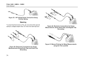
Electronic Connections for Scope Measurements Using Hook Clips and Alligator Clip Grounding Figure 39. Fluke 192B - 196B/C - 199B/C Users Manual Figure 38. Figure 40. Electronic Connections for Scope Measurements Using Hook Clips and Hook Clip Grounding 74 Figure 41. HF Voltage Probe Connection Using Ground Spring Warning To avoid electrical shock or fire, do not connect the ground spring to voltages higher than 30 Vrms from earth ground. Manual Probing for Meter Measurements using the Test Lead Set
Electronic Connections for Scope Measurements Using Hook Clips and Alligator Clip Grounding Figure 39. Fluke 192B - 196B/C - 199B/C Users Manual Figure 38. Figure 40. Electronic Connections for Scope Measurements Using Hook Clips and Hook Clip Grounding 74 Figure 41. HF Voltage Probe Connection Using Ground Spring Warning To avoid electrical shock or fire, do not connect the ground spring to voltages higher than 30 Vrms from earth ground. Manual Probing for Meter Measurements using the Test Lead Set

FE 192,196,199 C Users Manual
Page 84
... is picked up by reference lead B can be transmitted by parasitic capacitance to the analog input amplifier. 76 Parasitic capacitance between probes, instrument and environment MOTION/MOTOR CONTROLLER DC BUS + DIGITAL GROUND M - DC BUS Figure 43. Fluke 192B - 196B/C - 199B/C Users Manual ANALOG INPUT DIGITAL CONTROLLER ANALOG GROUND DIGITAL GROUND Figure 42.
... is picked up by reference lead B can be transmitted by parasitic capacitance to the analog input amplifier. 76 Parasitic capacitance between probes, instrument and environment MOTION/MOTOR CONTROLLER DC BUS + DIGITAL GROUND M - DC BUS Figure 43. Fluke 192B - 196B/C - 199B/C Users Manual ANALOG INPUT DIGITAL CONTROLLER ANALOG GROUND DIGITAL GROUND Figure 42.
FE 192,196,199 C Users Manual
Page 94
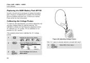
However, if replacement is needed, this should not be done by qualified personnel only. Contact your nearest Fluke center for 10:1 probes. The calibration consists of a high frequency adjustment and a dc calibration for more information. The dc calibration is already selected,... how to adjust the red and gray voltage probes for 100:1 probes. Figure 48. Calibrating the Voltage Probes To meet full user specifications, you need to calibrate the 10:1 voltage probes: 1 Display the input A key labels. 2 Open the Probe on A menu. Fluke 192B - 196B/C - 199B/C Users Manual ...
However, if replacement is needed, this should not be done by qualified personnel only. Contact your nearest Fluke center for 10:1 probes. The calibration consists of a high frequency adjustment and a dc calibration for more information. The dc calibration is already selected,... how to adjust the red and gray voltage probes for 100:1 probes. Figure 48. Calibrating the Voltage Probes To meet full user specifications, you need to calibrate the 10:1 voltage probes: 1 Display the input A key labels. 2 Open the Probe on A menu. Fluke 192B - 196B/C - 199B/C Users Manual ...
FE 192,196,199 C Users Manual
Page 95
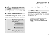
... indicates when the DC calibration has completed successfully. 9 Return. Connect the grey 10:1 voltage probe from the red input A jack to the red banana jack. Note When using 100:1 voltage probes, choose 100:1 attenuation to the black banana jack. Connect the reference lead to perform a ...HF adjustment. Automatic DC calibration is only possible for the gray 10:1 voltage probe. Repeat the procedure for 10:1 voltage probes. 87 Connect the reference lead to the black banana jack. (See Figure 48.) 7 Adjust the trimmer screw in...
... indicates when the DC calibration has completed successfully. 9 Return. Connect the grey 10:1 voltage probe from the red input A jack to the red banana jack. Note When using 100:1 voltage probes, choose 100:1 attenuation to the black banana jack. Connect the reference lead to perform a ...HF adjustment. Automatic DC calibration is only possible for the gray 10:1 voltage probe. Repeat the procedure for 10:1 voltage probes. 87 Connect the reference lead to the black banana jack. (See Figure 48.) 7 Adjust the trimmer screw in...
FE 192,196,199 C Users Manual
Page 97
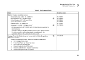
... The set includes the following items (not available separately): • 10:1 Voltage Probe (red) • 4-mm Test Probe for Probe Tip (red) • Hook Clip for Probe Tip (red) • Ground Lead with Hook Clip (red) • Ground... Lead with UL listed line plug adapter for Probe Tip (black) 8 Maintaining the Test Tool Parts and Accessories Ordering Code BC190/801 ...230 V rating of the BC190/808 is not for use in North America. Voltage Probe Set (Red), designed for use with the applicable National Requirements must be used. For other countries, ...
... The set includes the following items (not available separately): • 10:1 Voltage Probe (red) • 4-mm Test Probe for Probe Tip (red) • Hook Clip for Probe Tip (red) • Ground Lead with Hook Clip (red) • Ground... Lead with UL listed line plug adapter for Probe Tip (black) 8 Maintaining the Test Tool Parts and Accessories Ordering Code BC190/801 ...230 V rating of the BC190/808 is not for use in North America. Voltage Probe Set (Red), designed for use with the applicable National Requirements must be used. For other countries, ...
FE 192,196,199 C Users Manual
Page 98
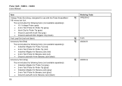
... Jack (gray) • Ground Lead with the Fluke ScopeMeter 190 series test tool. The set includes the following items (not available separately): • 10:1 Voltage Probe (gray) • 4-mm Test Probe for Probe Tip (gray) • Hook Clip for Probe Tip (gray) • Ground Lead with Hook ...The set includes the following items (not available separately): • Industrial Alligator for Probe Tip (red) • 2-mm Test Probe for Probe Tip (red) • Industrial Alligator for Banana Jack (red) • 2-mm Test Probe for Banana Jack (red) • Ground Lead with 4-mm Banana Jack (black...
... Jack (gray) • Ground Lead with the Fluke ScopeMeter 190 series test tool. The set includes the following items (not available separately): • 10:1 Voltage Probe (gray) • 4-mm Test Probe for Probe Tip (gray) • Hook Clip for Probe Tip (gray) • Ground Lead with Hook ...The set includes the following items (not available separately): • Industrial Alligator for Probe Tip (red) • 2-mm Test Probe for Probe Tip (red) • Industrial Alligator for Banana Jack (red) • 2-mm Test Probe for Banana Jack (red) • Ground Lead with 4-mm Banana Jack (black...
FE 192,196,199 C Users Manual
Page 99
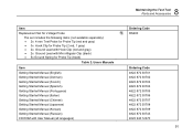
... with Mini Alligator Clip (black) • 5x Ground Spring for Probe Tip (black) Table 2. Item Replacement Set for Voltage Probe The set includes the following items (not available separately): • 2x 4-mm Test Probe for Probe Tip (red and gray) • 3x Hook Clip for Probe Tip (2 red, 1 gray) • 2x Ground Lead with Hook...
... with Mini Alligator Clip (black) • 5x Ground Spring for Probe Tip (black) Table 2. Item Replacement Set for Voltage Probe The set includes the following items (not available separately): • 2x 4-mm Test Probe for Probe Tip (red and gray) • 3x Hook Clip for Probe Tip (2 red, 1 gray) • 2x Ground Lead with Hook...
FE 192,196,199 C Users Manual
Page 104
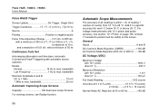
... Dual Input Oscilloscope Isolated Inputs A and B (Vertical) Bandwidth, DC Coupled FLUKE 199B/C 200 MHz (-3 dB) FLUKE 196B/C 100 MHz (-3 dB) FLUKE 192B 60 MHz (-3 dB) Lower Frequency Limit, AC Coupled with 10:1 probe 2 Hz (-3 dB) direct (1:1 5 Hz (-3 dB) Rise Time FLUKE 199B/C 1.7 ns FLUKE 196B/C 3.5 ns FLUKE 192B 5.8 ns Analog Bandwidth Limiters 20 MHz and 10 kHz...
... Dual Input Oscilloscope Isolated Inputs A and B (Vertical) Bandwidth, DC Coupled FLUKE 199B/C 200 MHz (-3 dB) FLUKE 196B/C 100 MHz (-3 dB) FLUKE 192B 60 MHz (-3 dB) Lower Frequency Limit, AC Coupled with 10:1 probe 2 Hz (-3 dB) direct (1:1 5 Hz (-3 dB) Rise Time FLUKE 199B/C 1.7 ns FLUKE 196B/C 3.5 ns FLUKE 192B 5.8 ns Analog Bandwidth Limiters 20 MHz and 10 kHz...
FE 192,196,199 C Users Manual
Page 106
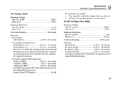
...Mode Rejection at 50, 60, or 400 Hz ......>60 dB DC Voltage (VDC) Maximum Voltage with 10:1 probe 1000 V direct (1:1 300 V Maximum Resolution with automatic source selection. Fluke 192B - 196B/C - 199B/C Users Manual Pulse Width Trigger Screen Update On Trigger, Single Shot Trigger Conditions ... ±(1.5 % + 10 counts) Normal Mode AC Rejection at 5 s to max. bandwidth Low Frequency 1 Hz to 28 °C. with 10:1 probe, add probe accuracy, see Replay function. 98 Automatic Scope Measurements The accuracy of all readings is within ± (% of reading + number of counts) from 18 &#...
...Mode Rejection at 50, 60, or 400 Hz ......>60 dB DC Voltage (VDC) Maximum Voltage with 10:1 probe 1000 V direct (1:1 300 V Maximum Resolution with automatic source selection. Fluke 192B - 196B/C - 199B/C Users Manual Pulse Width Trigger Screen Update On Trigger, Single Shot Trigger Conditions ... ±(1.5 % + 10 counts) Normal Mode AC Rejection at 5 s to max. bandwidth Low Frequency 1 Hz to 28 °C. with 10:1 probe, add probe accuracy, see Replay function. 98 Automatic Scope Measurements The accuracy of all readings is within ± (% of reading + number of counts) from 18 &#...
FE 192,196,199 C Users Manual
Page 107
...counts) For higher frequencies the instrument's frequency roll off starts affecting accuracy. 99 AC Voltage (VAC) Maximum Voltage with 10:1 probe 1000 V direct (1:1 300 V Maximum Resolution with 10:1 probe 1 mV direct (1:1 100 µV Full Scale Reading 1100 counts Accuracy DC to 60 Hz 1.5 % + 10 counts) ...+10 counts) AC coupled, low frequencies: 50 Hz direct (1:1 2.1 % + 10 counts) 60 Hz direct (1:1 1.9 % + 10 counts) With the 10:1 probe the low frequency roll off point will be lowered to 2 Hz, which improves the AC accuracy for maximum accuracy. When possible use DC coupling for...
...counts) For higher frequencies the instrument's frequency roll off starts affecting accuracy. 99 AC Voltage (VAC) Maximum Voltage with 10:1 probe 1000 V direct (1:1 300 V Maximum Resolution with 10:1 probe 1 mV direct (1:1 100 µV Full Scale Reading 1100 counts Accuracy DC to 60 Hz 1.5 % + 10 counts) ...+10 counts) AC coupled, low frequencies: 50 Hz direct (1:1 2.1 % + 10 counts) 60 Hz direct (1:1 1.9 % + 10 counts) With the 10:1 probe the low frequency roll off point will be lowered to 2 Hz, which improves the AC accuracy for maximum accuracy. When possible use DC coupling for...

FE 192,196,199 C Users Manual
Page 108
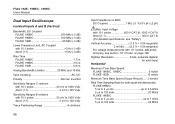
... 4.0 % to measure on pulse width modulated signals, like motor drive inverter outputs Principle ......... Fluke 192B - 196B/C - 199B/C Users Manual Amperes (AMP) With Optional Current Probe or Current Shunt Ranges same as VDC, VAC, VAC+DC Probe Sensitivity 100 µV/A, 1 mV/A, 10 mV/A, 100 mV/A, 1 V/A, 10 V/A, and ... current shunt accuracy) Peak Modes Max peak, Min peak, or pk-to-pk Maximum Voltage with 10:1 probe 1000 V direct (1:1 300 V Maximum Resolution with 10:1 probe 10 mV direct (1:1 1 mV Full Scale Reading 800 counts Accuracy Max peak or Min peak 0.2 division Peak-to-peak ...
... 4.0 % to measure on pulse width modulated signals, like motor drive inverter outputs Principle ......... Fluke 192B - 196B/C - 199B/C Users Manual Amperes (AMP) With Optional Current Probe or Current Shunt Ranges same as VDC, VAC, VAC+DC Probe Sensitivity 100 µV/A, 1 mV/A, 10 mV/A, 100 mV/A, 1 V/A, 10 V/A, and ... current shunt accuracy) Peak Modes Max peak, Min peak, or pk-to-pk Maximum Voltage with 10:1 probe 1000 V direct (1:1 300 V Maximum Resolution with 10:1 probe 10 mV direct (1:1 1 mV Full Scale Reading 800 counts Accuracy Max peak or Min peak 0.2 division Peak-to-peak ...
FE 192,196,199 C Users Manual
Page 109
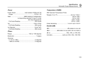
... 180 to +180 degrees Resolution 1 degree Accuracy 0.1 Hz to 1 MHz 2 degrees 1 MHz to 10 MHz 3 degrees 9 Specifications Automatic Scope Measurements Temperature (TEMP) With Optional Temperature Probe Ranges (°C or °F 40.0 to +100.0 ° -100 to +250 ° -100 to +500 ° -100 to +1000 ° -100 to + 2500 &#...176; Probe Sensitivity 1 mV/°C and 1 mV/°F Decibel (dB) dBV dB relative to one volt dBm dB relative to one mW in 50 Ω or 600 &#...
... 180 to +180 degrees Resolution 1 degree Accuracy 0.1 Hz to 1 MHz 2 degrees 1 MHz to 10 MHz 3 degrees 9 Specifications Automatic Scope Measurements Temperature (TEMP) With Optional Temperature Probe Ranges (°C or °F 40.0 to +100.0 ° -100 to +250 ° -100 to +500 ° -100 to +1000 ° -100 to + 2500 &#...176; Probe Sensitivity 1 mV/°C and 1 mV/°F Decibel (dB) dBV dB relative to one volt dBm dB relative to one mW in 50 Ω or 600 &#...
