
FE 1587-1577 Users Manual
Page 1
Printed in USA All product names are trademarks of their respective companies. ® 1587/1577 Insulation Multimeters Users Manual All rights reserved. PN 2401027 April 2005 Rev.1, 1/06 © 2005-2006 Fluke Corporation.
Printed in USA All product names are trademarks of their respective companies. ® 1587/1577 Insulation Multimeters Users Manual All rights reserved. PN 2401027 April 2005 Rev.1, 1/06 © 2005-2006 Fluke Corporation.

FE 1587-1577 Users Manual
Page 4
1587/1577 Users Manual Making Basic Measurements 16 Measuring AC and DC Voltage 17 Measuring Temperature (Model 1587 and 1587T 18 Measuring Resistance 19 Measuring Capacitance (Model 1587 and 1587T 19 Testing for Continuity 20 Testing Diodes (Model 1587 and 1587T 21 Measuring AC or DC Current 22 Testing Insulation ...24 Measuring Frequency...
1587/1577 Users Manual Making Basic Measurements 16 Measuring AC and DC Voltage 17 Measuring Temperature (Model 1587 and 1587T 18 Measuring Resistance 19 Measuring Capacitance (Model 1587 and 1587T 19 Testing for Continuity 20 Testing Diodes (Model 1587 and 1587T 21 Measuring AC or DC Current 22 Testing Insulation ...24 Measuring Frequency...

FE 1587-1577 Users Manual
Page 5
Contents (continued) Frequency Counter Sensitivity 35 Capacitance (1587 and 1587T Only 35 Temperature Measurement (1587 and 1587T Only 36 Insulation Specifications 36 Model 1587 ...37 Model 1577 ...37 Model 1587T...38 iii
Contents (continued) Frequency Counter Sensitivity 35 Capacitance (1587 and 1587T Only 35 Temperature Measurement (1587 and 1587T Only 36 Insulation Specifications 36 Model 1587 ...37 Model 1577 ...37 Model 1587T...38 iii

FE 1587-1577 Users Manual
Page 9
Buttons ...6 3. Input Terminals...11 5. Low Pass Filter ...15 6. Testing for Continuity...20 11. Testing Diodes ...21 12. Testing the Fuse...27 16. Measuring Resistance ...19 9. Measuring Temperature ...18 8. Measuring AC or DC Current 23 13. Testing Insulation ...25 14. Replacing the Fuse and Battery 28 vii Rotary Switch ...5 2. List of Figures Figure Title Page 1. Measuring Capacitance...19 10. Measuring Frequency...26 15. Display Indicators ...8 4. Measuring AC and DC Voltage 17 7.
Buttons ...6 3. Input Terminals...11 5. Low Pass Filter ...15 6. Testing for Continuity...20 11. Testing Diodes ...21 12. Testing the Fuse...27 16. Measuring Resistance ...19 9. Measuring Temperature ...18 8. Measuring AC or DC Current 23 13. Testing Insulation ...25 14. Replacing the Fuse and Battery 28 vii Rotary Switch ...5 2. List of Figures Figure Title Page 1. Measuring Capacitance...19 10. Measuring Frequency...26 15. Display Indicators ...8 4. Measuring AC and DC Voltage 17 7.
FE 1587-1577 Users Manual
Page 11
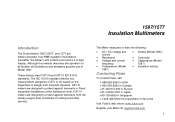
... examples assume use of danger from anywhere in Singapore +1-425-446-5500 from transient impulses. 1587/1577 Insulation Multimeters Introduction The Fluke Models 1587,1587T, and 1577 are designed to protect against transients in Fixed equipment installations at : register.fluke.com 1 CAT III meters are designed to IV) based on the magnitude of Model 1587...
... examples assume use of danger from anywhere in Singapore +1-425-446-5500 from transient impulses. 1587/1577 Insulation Multimeters Introduction The Fluke Models 1587,1587T, and 1577 are designed to protect against transients in Fixed equipment installations at : register.fluke.com 1 CAT III meters are designed to IV) based on the magnitude of Model 1587...
FE 1587-1577 Users Manual
Page 13
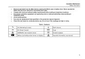
Battery (Low battery when shown on display.) J I T W Earth Ground Fuse Double Insulated Important information; B F X b Table 1. see manual 3 Never operate the Meter with the cover removed or the battery door open. • Comply with local and national safety ... for continuity before opening the Meter case or battery door. Do not use . Symbols AC (Alternating Current) DC (Direct Current) WARNING: risk of electric shock. Insulation Multimeters Safety Information • Remove test leads from the Meter before use if the readings are high or noisy.
Battery (Low battery when shown on display.) J I T W Earth Ground Fuse Double Insulated Important information; B F X b Table 1. see manual 3 Never operate the Meter with the cover removed or the battery door open. • Comply with local and national safety ... for continuity before opening the Meter case or battery door. Do not use . Symbols AC (Alternating Current) DC (Direct Current) WARNING: risk of electric shock. Insulation Multimeters Safety Information • Remove test leads from the Meter before use if the readings are high or noisy.

FE 1587-1577 Users Manual
Page 14
... is always disabled in the MIN MAX AVG recording mode, AutoHold mode, insulation test active, or if the auto power off feature has been disabled by pressing the blue button when the Meter is displayed. 1587/1577 Users Manual Accessories Model Leads Probes Clips 1587 and 1587T TL224 TP74 AC285... 1577 TL224 TL74 AC285 Unsafe Voltage To alert you to the presence of Sleep mode when a key is...
... is always disabled in the MIN MAX AVG recording mode, AutoHold mode, insulation test active, or if the auto power off feature has been disabled by pressing the blue button when the Meter is displayed. 1587/1577 Users Manual Accessories Model Leads Probes Clips 1587 and 1587T TL224 TP74 AC285... 1577 TL224 TL74 AC285 Unsafe Voltage To alert you to the presence of Sleep mode when a key is...
FE 1587-1577 Users Manual
Page 15
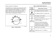
... Figure 1 and described in memory when the Meter is the default temperature measurement unit. E DC mV 0.1 mV to + 998 °F). Figure 1. Rotary Switch bav02f.eps Insulation Multimeters Rotary Switch Positions Table 2. k (1587 and 1587T only) Temperature from 0.1 Ω to 1000 V. K (1587 and 1587T only) C AC voltage with blue letters). DC voltage...
... Figure 1 and described in memory when the Meter is the default temperature measurement unit. E DC mV 0.1 mV to + 998 °F). Figure 1. Rotary Switch bav02f.eps Insulation Multimeters Rotary Switch Positions Table 2. k (1587 and 1587T only) Temperature from 0.1 Ω to 1000 V. K (1587 and 1587T only) C AC voltage with blue letters). DC voltage...

FE 1587-1577 Users Manual
Page 16
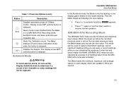
... The buttons are shown in Figure 2 and described in this function. 1587/1577 Users Manual Table 2. Performs insulation test with the rotary switch. Rotary Switch Selections (cont.) Switch Position X O (1587 and 1587T only) c a INSULATION Measurement Function Continuity test. There is turned off. Ohms from 0.01 mA ...1000 V source on the 1577 or 50 V (default) and 100 V on at 100 Ω. The last selected high voltage setting is retained in memory when the Meter is no ranging in Table 3. AC mA from 3.00 mA to activate smoothing during insulation testing (1587 only). ...
... The buttons are shown in Figure 2 and described in this function. 1587/1577 Users Manual Table 2. Performs insulation test with the rotary switch. Rotary Switch Selections (cont.) Switch Position X O (1587 and 1587T only) c a INSULATION Measurement Function Continuity test. There is turned off. Ohms from 0.01 mA ...1000 V source on the 1577 or 50 V (default) and 100 V on at 100 Ω. The last selected high voltage setting is retained in memory when the Meter is no ranging in Table 3. AC mA from 3.00 mA to activate smoothing during insulation testing (1587 only). ...
FE 1587-1577 Users Manual
Page 17
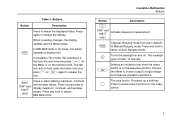
...or t again to Auto Ranging mode. Functions as a shift key. Table 3. Buttons Button Description Press to Manual Ranging mode. In Insulation Test mode, this button operates a display hold to return to release the lock. r Changes Ranging mode from Auto (default) to freeze... on and off after 10 minutes. The test lock acts to hold to access blue functions on the INSULATION position. Press and hold . The blue button. Insulation Multimeters Buttons Button Description f (1587 and 1587T only) Activate frequency measurement. Press successively to source (output...
...or t again to Auto Ranging mode. Functions as a shift key. Table 3. Buttons Button Description Press to Manual Ranging mode. In Insulation Test mode, this button operates a display hold to return to release the lock. r Changes Ranging mode from Auto (default) to freeze... on and off after 10 minutes. The test lock acts to hold to access blue functions on the INSULATION position. Press and hold . The blue button. Insulation Multimeters Buttons Button Description f (1587 and 1587T only) Activate frequency measurement. Press successively to source (output...
FE 1587-1577 Users Manual
Page 19
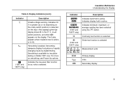
...Indicates 30 V or greater (ac or dc depending on the rotary switch position) is active. Table 4. The Z also appears when insulation test is selected. Indicates display hold is detected on the display. Smoothing is available for ac volts is active, or in the ...B, C, or E switch positions, and when batt appears on the input. Insulation Multimeters Understanding the Display Indicator Description Y S Indicates AutoHold is selected nF, µF, ° C, ° F, Measurement units AC, DC, Hz, kHZ...
...Indicates 30 V or greater (ac or dc depending on the rotary switch position) is active. Table 4. The Z also appears when insulation test is selected. Indicates display hold is detected on the display. Smoothing is available for ac volts is active, or in the ...B, C, or E switch positions, and when batt appears on the input. Insulation Multimeters Understanding the Display Indicator Description Y S Indicates AutoHold is selected nF, µF, ° C, ° F, Measurement units AC, DC, Hz, kHZ...

FE 1587-1577 Users Manual
Page 20
...of the c position. The t button is disabled until the battery is replaced. Model detect error. Insulation test indicator. Appears when an open thermocouple is displayed. 1587/1577 Users Manual Table 4. Appears when insulation test voltage is on the secondary display and indicates that the battery is too low for... insulation test: 50, 100, 250, 500 (default) or 1000 V on the 1587. 500 (default) and 1000 V ranges available on the 1577. 50 (default) and 100 V on the 1587T. The b also appears when ...
...of the c position. The t button is disabled until the battery is replaced. Model detect error. Insulation test indicator. Appears when an open thermocouple is displayed. 1587/1577 Users Manual Table 4. Appears when insulation test voltage is on the secondary display and indicates that the battery is too low for... insulation test: 50, 100, 250, 500 (default) or 1000 V on the 1587. 500 (default) and 1000 V ranges available on the 1577. 50 (default) and 100 V on the 1587T. The b also appears when ...
FE 1587-1577 Users Manual
Page 21
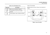
Error Messages (cont.) Message Description diSc Meter cannot discharge a capacitor. EPPr Err Invalid EEProm data. Have the Meter serviced. Input Terminals bav04f.eps 11 CAL Invalid calibration data. Calibrate the Meter. Table 5. Err Insulation Multimeters Input Terminals Input Terminals Input terminals are shown in Figure 4 and described in Table 6. 1 3 2 4 Figure 4.
Error Messages (cont.) Message Description diSc Meter cannot discharge a capacitor. EPPr Err Invalid EEProm data. Have the Meter serviced. Input Terminals bav04f.eps 11 CAL Invalid calibration data. Calibrate the Meter. Table 5. Err Insulation Multimeters Input Terminals Input Terminals Input terminals are shown in Figure 4 and described in Table 6. 1 3 2 4 Figure 4.
FE 1587-1577 Users Manual
Page 22
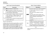
...battery until the button is pressed. Note Power Up options are cancelled when the Meter is released. q input terminal for insulation test. The remaining positions show all of the Meter. INSULATION switch position initiates a fully loaded battery test and displays the charge level of rapidly changing inputs by digital filtering. until the...) measurements. C switch position displays the software version number. C Input terminal for all LCD segments. E switch position displays the model number. The display shows S - - - 1587/1577 Users Manual . Item A B Table 6.
...battery until the button is pressed. Note Power Up options are cancelled when the Meter is released. q input terminal for insulation test. The remaining positions show all of the Meter. INSULATION switch position initiates a fully loaded battery test and displays the charge level of rapidly changing inputs by digital filtering. until the...) measurements. C switch position displays the software version number. C Input terminal for all LCD segments. E switch position displays the model number. The display shows S - - - 1587/1577 Users Manual . Item A B Table 6.
FE 1587-1577 Users Manual
Page 23
...or noisy readings will not be used to determine if a circuit is in a MIN MAX AVG Recording mode, AutoHold mode, and when performing an insulation test. MIN MAX AVG Recording Mode The MIN MAX AVG mode records minimum and maximum input values. Power-Up Options (cont.) Button Description G (... until the button is released. Starts the Calibration mode. The Meter displays Cal and enters Calibration mode when the button is released. Insulation Multimeters AutoHold Mode In the AutoHold mode, the Meter holds the reading on the display until the button is released. This mode can...
...or noisy readings will not be used to determine if a circuit is in a MIN MAX AVG Recording mode, AutoHold mode, and when performing an insulation test. MIN MAX AVG Recording Mode The MIN MAX AVG mode records minimum and maximum input values. Power-Up Options (cont.) Button Description G (... until the button is released. Starts the Calibration mode. The Meter displays Cal and enters Calibration mode when the button is released. Insulation Multimeters AutoHold Mode In the AutoHold mode, the Meter holds the reading on the display until the button is released. This mode can...
FE 1587-1577 Users Manual
Page 25
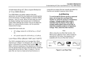
.... These offset readings are typically generated by pressing the r button. Low Pass Filter bav16f.eps 15 The low pass filter can improve measurement performance on Insulation Multimeters Understanding AC Zero Input Behavior of hazardous voltage. Voltages greater than what is indicated may fluctuate due to detect the possible presence of True...
.... These offset readings are typically generated by pressing the r button. Low Pass Filter bav16f.eps 15 The low pass filter can improve measurement performance on Insulation Multimeters Understanding AC Zero Input Behavior of hazardous voltage. Voltages greater than what is indicated may fluctuate due to detect the possible presence of True...

FE 1587-1577 Users Manual
Page 27
Measuring AC and DC Voltage Volts AC LO HOLD MIN MAX TEST Volts DC LO HOLD MIN MAX TEST Insulation Multimeters Making Basic Measurements Millivolts DC LO HOLD MIN MAX TEST Figure 6. Measuring AC and DC Voltage bav05f.eps 17
Measuring AC and DC Voltage Volts AC LO HOLD MIN MAX TEST Volts DC LO HOLD MIN MAX TEST Insulation Multimeters Making Basic Measurements Millivolts DC LO HOLD MIN MAX TEST Figure 6. Measuring AC and DC Voltage bav05f.eps 17

FE 1587-1577 Users Manual
Page 29
Measuring Resistance bav06f.eps Figure 9. Measuring Resistance . LO HOLD MIN MAX TEST Figure 8. LO HOLD MIN MAX TEST Insulation Multimeters Making Basic Measurements Measuring Capacitance (Model 1587 and 1587T) . Measuring Capacitance bav07f.eps 19
Measuring Resistance bav06f.eps Figure 9. Measuring Resistance . LO HOLD MIN MAX TEST Figure 8. LO HOLD MIN MAX TEST Insulation Multimeters Making Basic Measurements Measuring Capacitance (Model 1587 and 1587T) . Measuring Capacitance bav07f.eps 19

FE 1587-1577 Users Manual
Page 31
Testing Diodes Insulation Multimeters Making Basic Measurements Bad Diode LO HOLD MIN MAX TEST and Shorted Constant Beep bav10f.eps 21 Testing Diodes (Model 1587 and 1587T) . Good Diode LO HOLD MIN MAX TEST Good Diode LO HOLD MIN MAX TEST Bad Diode LO HOLD MIN MAX TEST Forward Bias Open Single Beep Reverse Bias Figure 11.
Testing Diodes Insulation Multimeters Making Basic Measurements Bad Diode LO HOLD MIN MAX TEST and Shorted Constant Beep bav10f.eps 21 Testing Diodes (Model 1587 and 1587T) . Good Diode LO HOLD MIN MAX TEST Good Diode LO HOLD MIN MAX TEST Bad Diode LO HOLD MIN MAX TEST Forward Bias Open Single Beep Reverse Bias Figure 11.
FE 1587-1577 Users Manual
Page 33
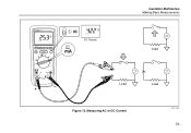
LO HOLD MIN MAX TEST LO HOLD MIN MAX TEST DC Display Insulation Multimeters Making Basic Measurements Load Load Figure 12. Measuring AC or DC Current Load bav11f.eps 23
LO HOLD MIN MAX TEST LO HOLD MIN MAX TEST DC Display Insulation Multimeters Making Basic Measurements Load Load Figure 12. Measuring AC or DC Current Load bav11f.eps 23

