Calibration Guide
Page 1
Specifications are trademarks of their respective companies. 123B/124B/125B Industrial ScopeMeter Calibration Manual May 2016 ©2016 Fluke Corporation. All rights reserved. All product names are subject to change without notice.
Specifications are trademarks of their respective companies. 123B/124B/125B Industrial ScopeMeter Calibration Manual May 2016 ©2016 Fluke Corporation. All rights reserved. All product names are subject to change without notice.
Calibration Guide
Page 9
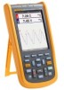
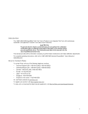
...or personal injury, do so. The information provided in this manual unless you are qualified to the 123B/124B/125B Industrial ScopeMeter Users Manual at www.fluke.com. This manual provides all the information necessary to -use of the following telephone numbers: • Technical..., and 'paperless' recorder in one of qualified personnel only. How to Contact Fluke To contact Fluke, call one easy-to perform basic maintenance and make calibration adjustments. Introduction The 123B/124B/125B ScopeMeter® (the Test Tool or Product) is for the use instrument. To register...
...or personal injury, do so. The information provided in this manual unless you are qualified to the 123B/124B/125B Industrial ScopeMeter Users Manual at www.fluke.com. This manual provides all the information necessary to -use of the following telephone numbers: • Technical..., and 'paperless' recorder in one of qualified personnel only. How to Contact Fluke To contact Fluke, call one easy-to perform basic maintenance and make calibration adjustments. Introduction The 123B/124B/125B ScopeMeter® (the Test Tool or Product) is for the use instrument. To register...
Calibration Guide
Page 11
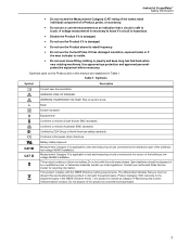
...applicable to the equipment types in the WEEE Directive Annex I, this electrical/electronic product in domestic household waste. Contact your authorized Fluke Service Center for recycling information. Do not dispose of this manual are explained in this product as category 9 "Monitoring and ... touch. The affixed label indicates that a circuit is safe to the distribution part of the building's low-voltage MAINS installation. Industrial ScopeMeter Safety Information • Do not exceed the Measurement Category (CAT) rating of the lowest rated individual component of a Product,...
...applicable to the equipment types in the WEEE Directive Annex I, this electrical/electronic product in domestic household waste. Contact your authorized Fluke Service Center for recycling information. Do not dispose of this manual are explained in this product as category 9 "Monitoring and ... touch. The affixed label indicates that a circuit is safe to the distribution part of the building's low-voltage MAINS installation. Industrial ScopeMeter Safety Information • Do not exceed the Measurement Category (CAT) rating of the lowest rated individual component of a Product,...
Calibration Guide
Page 13
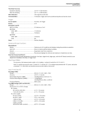
... Source A, B Sensitivity A and B @ DC to 5 MHz 0.5 divisions or 5 mV @ 40 MHz 125B, 124B 1.5 divisions 123B 4 divisions @ 60 MHz 125B, 124B 4 divisions 123B NA Slope Positive, Negative Advanced Scope Functions Display Modes Normal Captures up to 25 ns glitches... and displays analog-like persistence waveform. For voltage measurements with 10:1 probe, add probe uncertainty +1 %. Industrial ScopeMeter Specifications Time Base...
... Source A, B Sensitivity A and B @ DC to 5 MHz 0.5 divisions or 5 mV @ 40 MHz 125B, 124B 1.5 divisions 123B 4 divisions @ 60 MHz 125B, 124B 4 divisions 123B NA Slope Positive, Negative Advanced Scope Functions Display Modes Normal Captures up to 25 ns glitches... and displays analog-like persistence waveform. For voltage measurements with 10:1 probe, add probe uncertainty +1 %. Industrial ScopeMeter Specifications Time Base...

Calibration Guide
Page 15
Industrial ScopeMeter Specifications with iFlex clamp Ranges 20 A/division Maximum Current 75 A @ 40 Hz to 300 Hz Frequency derating: I * F
Industrial ScopeMeter Specifications with iFlex clamp Ranges 20 A/division Maximum Current 75 A @ 40 Hz to 300 Hz Frequency derating: I * F

Calibration Guide
Page 17
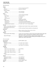
.../s Record Size Internal memory 400 M samples Recorded Time Span internal memory 15 minutes at 500 μs/div 11 hours at 20 ms/div 125B, 124B Record Size SD card 15 G samples Recorded Time Span SD card 11 hours at 500 μs/div 14 days at 20 ms...), 51st ±(30 % + 5 counts) Frequency of Meter measurements over time or as a waveform recorder display that plots all the captured samples. Industrial ScopeMeter Specifications Recorder The recorder captures meter readings in Meter Recorder mode or continuously captures waveform samples in Amp and Watt 10 % Field Bus Measurements...
.../s Record Size Internal memory 400 M samples Recorded Time Span internal memory 15 minutes at 500 μs/div 11 hours at 20 ms/div 125B, 124B Record Size SD card 15 G samples Recorded Time Span SD card 11 hours at 500 μs/div 14 days at 20 ms...), 51st ±(30 % + 5 counts) Frequency of Meter measurements over time or as a waveform recorder display that plots all the captured samples. Industrial ScopeMeter Specifications Recorder The recorder captures meter readings in Meter Recorder mode or continuously captures waveform samples in Amp and Watt 10 % Field Bus Measurements...
Calibration Guide
Page 18
... to PC/laptop Transfer screen dumps (bitmaps), settings and data using OC4USB optically isolated USB adapter/cable, (optional), using FlukeView® ScopeMeter® software for Windows®. 123B/124B/125B Calibration Manual Miscellaneous Display Type 5.7-inch color active matrix TFT Resolution 640 pixels x 480 pixels Waveform Display Vertical 10 div of 40...
... to PC/laptop Transfer screen dumps (bitmaps), settings and data using OC4USB optically isolated USB adapter/cable, (optional), using FlukeView® ScopeMeter® software for Windows®. 123B/124B/125B Calibration Manual Miscellaneous Display Type 5.7-inch color active matrix TFT Resolution 640 pixels x 480 pixels Waveform Display Vertical 10 div of 40...

Calibration Guide
Page 19
...with leads 600 Vrms CAT IV for domestic purposes. Voltage Between Test Tool and STL120-IV Reference and Earth Ground The Fluke 12xB series, including standard accessories, conforms to the EEC directive 2004/108/EC for use in business environments and not... EN/IEC60529 Safety General IEC 61010-1: Pollution Degree 2 Measurement IEC 61010-2-033: CAT IV 600 V / CAT III 750 V Max. Industrial ScopeMeter Specifications Electromagnetic Compatibility (EMC) International IEC 61326-1: Industrial CISPR 11: Group 1, Class A Group 1: Equipment has intentionally generated and/or uses...
...with leads 600 Vrms CAT IV for domestic purposes. Voltage Between Test Tool and STL120-IV Reference and Earth Ground The Fluke 12xB series, including standard accessories, conforms to the EEC directive 2004/108/EC for use in business environments and not... EN/IEC60529 Safety General IEC 61010-1: Pollution Degree 2 Measurement IEC 61010-2-033: CAT IV 600 V / CAT III 750 V Max. Industrial ScopeMeter Specifications Electromagnetic Compatibility (EMC) International IEC 61326-1: Industrial CISPR 11: Group 1, Class A Group 1: Equipment has intentionally generated and/or uses...
Calibration Guide
Page 21
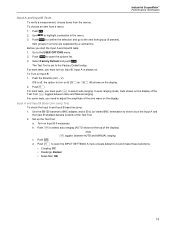
..., you must pushto select auto ranging. If B is off ) shows on / off , the option to the USER OPTIONS menu. 2. Industrial ScopeMeter Performance Verification Input A and Input B Tests To verify a measurement, choose items from a menu: 1. Item groups in the menu. 3. V). Input A and Input B Base Line Jump...
..., you must pushto select auto ranging. If B is off ) shows on / off , the option to the USER OPTIONS menu. 2. Industrial ScopeMeter Performance Verification Input A and Input B Tests To verify a measurement, choose items from a menu: 1. Item groups in the menu. 3. V). Input A and Input B Base Line Jump...
Calibration Guide
Page 23
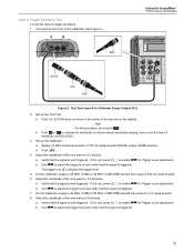
... Level adjustment. On the Calibrator, supply a 25 MHz (123B) or 40 MHz (124B/125B) leveled sine wave of the top row on 200 mV/div. 3. If it is well triggered. A B BNC Industrial ScopeMeter Performance Verification 5522A CALIBRATOR BB120 50Ω BNC Figure 3. Push if AUTO...is not, press to enable for Trigger Level adjustment. On the Calibrator, supply a 40 MHz (123B) or 60 MHz (124B/125B) leveled sine wave of the sine wave to -peak. 8. Adjust the amplitude of 1.8 V peak-to 4 divisions. If it is well triggered. Adjust...
... Level adjustment. On the Calibrator, supply a 25 MHz (123B) or 40 MHz (124B/125B) leveled sine wave of the top row on 200 mV/div. 3. If it is well triggered. A B BNC Industrial ScopeMeter Performance Verification 5522A CALIBRATOR BB120 50Ω BNC Figure 3. Push if AUTO...is not, press to enable for Trigger Level adjustment. On the Calibrator, supply a 40 MHz (123B) or 60 MHz (124B/125B) leveled sine wave of the sine wave to -peak. 8. Adjust the amplitude of 1.8 V peak-to 4 divisions. If it is well triggered. Adjust...

Calibration Guide
Page 25
A B BNC Industrial ScopeMeter Performance Verification 5522A CALIBRATOR BB120 50Ω BNC Figure 4. Push . e. f. Push to open the INPUT B MEASUREMENTS menu. Supply a leveled sine wave ...
A B BNC Industrial ScopeMeter Performance Verification 5522A CALIBRATOR BB120 50Ω BNC Figure 4. Push . e. f. Push to open the INPUT B MEASUREMENTS menu. Supply a leveled sine wave ...

Calibration Guide
Page 27
...mV peak-to adjust the trigger level and verify that the signal is triggered. b. On the Calibrator, supply a 25 MHz (123B) or 40 MHz (124B/125B) leveled sine wave of the sine wave to -peak. 8. If it is well triggered. b. Use to -peak. 6. Verify that the ... the Test Tool to enable for positive or negative slope triggering: 1. The trigger icon () indicates the trigger level. 5. Industrial ScopeMeter Performance Verification 4. Verify that the signal is not, press to the Calibrator. If it is triggered. 7.
...mV peak-to adjust the trigger level and verify that the signal is triggered. b. On the Calibrator, supply a 25 MHz (123B) or 40 MHz (124B/125B) leveled sine wave of the sine wave to -peak. 8. If it is well triggered. b. Use to -peak. 6. Verify that the ... the Test Tool to enable for positive or negative slope triggering: 1. The trigger icon () indicates the trigger level. 5. Industrial ScopeMeter Performance Verification 4. Verify that the signal is not, press to the Calibrator. If it is triggered. 7.

Calibration Guide
Page 29
... the Test Tool and that the voltage on the display. 18. Verify traces do not show on the Calibrator to clear the display. 31. Industrial ScopeMeter Performance Verification 16. Verify that Waiting shows on the status line at the top of the Test Tool and that Waiting shows on the...
... the Test Tool and that the voltage on the display. 18. Verify traces do not show on the Calibrator to clear the display. 31. Industrial ScopeMeter Performance Verification 16. Verify that Waiting shows on the status line at the top of the Test Tool and that Waiting shows on the...

Calibration Guide
Page 31
Industrial ScopeMeter Performance Verification d. f. ii. Table 4. Input A-B DC Limit 014.4 to 015.6[2] 029.3 to 030.7[2] 059.2 to 060.8 148.7 to 151.3 298.0 to 302.0 497.0 to ...
Industrial ScopeMeter Performance Verification d. f. ii. Table 4. Input A-B DC Limit 014.4 to 015.6[2] 029.3 to 030.7[2] 059.2 to 060.8 148.7 to 151.3 298.0 to 302.0 497.0 to ...

Calibration Guide
Page 33
... • Noise filter: OFF c. See Figure 6. 2. Select Peak and push to select auto ranging (AUTO shows at the top of the display). ii. d. Industrial ScopeMeter Performance Verification Input A and Input B AC Input Coupling Test To test the Input A and B ac input coupling: 1. Set up the Test Tool: a. Push ...
... • Noise filter: OFF c. See Figure 6. 2. Select Peak and push to select auto ranging (AUTO shows at the top of the display). ii. d. Industrial ScopeMeter Performance Verification Input A and Input B AC Input Coupling Test To test the Input A and B ac input coupling: 1. Set up the Test Tool: a. Push ...

Calibration Guide
Page 35
... CalibratorCalibrator: a. g. b. Volts Peak Verification Points 1.5 V Calibrator Output V rms (Sine Calibrator Frequency 1 kHz Limit A-B -2 degrees to the Calibrator. Connect the Test Tool to +2 degrees Harmonics Test (125B) To test the harmonics: 1. b. Supply a square wave. Setup the Test Tool: a. Push to open the SETTINGS menu. f. Supply 2.5 Vpp, 60 Hz (NORMAL output, WAVE...
... CalibratorCalibrator: a. g. b. Volts Peak Verification Points 1.5 V Calibrator Output V rms (Sine Calibrator Frequency 1 kHz Limit A-B -2 degrees to the Calibrator. Connect the Test Tool to +2 degrees Harmonics Test (125B) To test the harmonics: 1. b. Supply a square wave. Setup the Test Tool: a. Push to open the SETTINGS menu. f. Supply 2.5 Vpp, 60 Hz (NORMAL output, WAVE...

Calibration Guide
Page 37
... 9. b. Table 9. Setup V ac and V dc for Input B on the Test Tool: a. i. k. Push to the center. 7. Push to open the INPUT B MEASUREMENTS menu. Industrial ScopeMeter Performance Verification 2. Note For this procedure, do not push . Push . Push to open the INPUT B MEASUREMENTS menu. The range is listed...
... 9. b. Table 9. Setup V ac and V dc for Input B on the Test Tool: a. i. k. Push to the center. 7. Push to open the INPUT B MEASUREMENTS menu. Industrial ScopeMeter Performance Verification 2. Note For this procedure, do not push . Push . Push to open the INPUT B MEASUREMENTS menu. The range is listed...

Calibration Guide
Page 39
... 25 Ω b. Set up the Calibrator: a. On the Calibrator, supply 35 Ω. 6. Push . 4. On the Calibrator, supply 1 V DC. 6. Supply the Range and Output. Industrial ScopeMeter Performance Verification 3. Push . Compare the Input A main reading to open the INPUT A MEASUREMENTS menu. See Figure 9. 2. Connect the Test Tool to the Calibrator...
... 25 Ω b. Set up the Calibrator: a. On the Calibrator, supply 35 Ω. 6. Push . 4. On the Calibrator, supply 1 V DC. 6. Supply the Range and Output. Industrial ScopeMeter Performance Verification 3. Push . Compare the Input A main reading to open the INPUT A MEASUREMENTS menu. See Figure 9. 2. Connect the Test Tool to the Calibrator...
Calibration Guide
Page 41
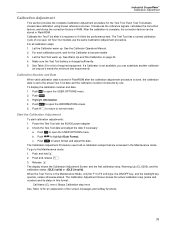
... shows the actual calibration step (name and number) and its status in the Maintenance Mode, only the F1 to open the USER OPTIONS menu. 2. Industrial ScopeMeter Calibration Adjustment Calibration Adjustment This section provides the complete Calibration Adjustment procedure for an explanation of the screen messages and softkey functions. 33 After...
... shows the actual calibration step (name and number) and its status in the Maintenance Mode, only the F1 to open the USER OPTIONS menu. 2. Industrial ScopeMeter Calibration Adjustment Calibration Adjustment This section provides the complete Calibration Adjustment procedure for an explanation of the screen messages and softkey functions. 33 After...

Calibration Guide
Page 43
.... c. Connect the Calibrator Scope Out to select the next calibration step. 6. Push to CH A & CH B with a 50 Ω terminator. A B BB120 50Ω BNC Industrial ScopeMeter Calibration Adjustment 5522A CALIBRATOR BB120 PM9093/001 PM9091/001 (1.5 m) PM9092/001 (0.5 m) Figure 10. HF Gain Calibration Input Connections 3. Set up the Calibrator: a. Supply a 1 kHz...
.... c. Connect the Calibrator Scope Out to select the next calibration step. 6. Push to CH A & CH B with a 50 Ω terminator. A B BB120 50Ω BNC Industrial ScopeMeter Calibration Adjustment 5522A CALIBRATOR BB120 PM9093/001 PM9091/001 (1.5 m) PM9092/001 (0.5 m) Figure 10. HF Gain Calibration Input Connections 3. Set up the Calibrator: a. Supply a 1 kHz...
