Calibration Guide
Page 1
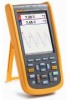
123B/124B/125B Industrial ScopeMeter Calibration Manual May 2016 ©2016 Fluke Corporation. All product names are subject to change without notice. All rights reserved. Specifications are trademarks of their respective companies.
123B/124B/125B Industrial ScopeMeter Calibration Manual May 2016 ©2016 Fluke Corporation. All product names are subject to change without notice. All rights reserved. Specifications are trademarks of their respective companies.
Calibration Guide
Page 9
The information provided in the world: +1-425-446-5500 Or, visit Fluke's website at www.fluke.com. How to Contact Fluke To contact Fluke, call one easy-to the 123B/124B/125B Industrial ScopeMeter Users Manual at www.fluke.com. For complete operating instructions, refer to -use of the following telephone numbers: • Technical Support USA: 1-800-44...
The information provided in the world: +1-425-446-5500 Or, visit Fluke's website at www.fluke.com. How to Contact Fluke To contact Fluke, call one easy-to the 123B/124B/125B Industrial ScopeMeter Users Manual at www.fluke.com. For complete operating instructions, refer to -use of the following telephone numbers: • Technical Support USA: 1-800-44...
Calibration Guide
Page 11
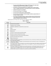
...approved eye protection and approved personalprotective equipment where necessary. This product contains a Lithium-ion battery. Contact your authorized Fluke Service Center for recycling information. RISK OF DANGER. WARNING. HAZARDOUS VOLTAGE. Earth Double Insulated Equipotential Conforms to relevant...Directive Annex I, this manual are explained in domestic household waste. Do not mix with the WEEE Directive marking requirements. Industrial ScopeMeter Safety Information • Do not exceed the Measurement Category (CAT) rating of the lowest rated individual component...
...approved eye protection and approved personalprotective equipment where necessary. This product contains a Lithium-ion battery. Contact your authorized Fluke Service Center for recycling information. RISK OF DANGER. WARNING. HAZARDOUS VOLTAGE. Earth Double Insulated Equipotential Conforms to relevant...Directive Annex I, this manual are explained in domestic household waste. Do not mix with the WEEE Directive marking requirements. Industrial ScopeMeter Safety Information • Do not exceed the Measurement Category (CAT) rating of the lowest rated individual component...
Calibration Guide
Page 13
... gap, and hold-off. Dual Input Meter The accuracy of all measurements is within ±(% of reading + number of counts) from a waveform. Industrial ScopeMeter Specifications Time Base Accuracy Equivalent sampling 0.4 % + 0.025 time/div) Real time sampling 0.1 % + 0.025 time/div) Glitch Detection 25... Source A, B Sensitivity A and B @ DC to 5 MHz 0.5 divisions or 5 mV @ 40 MHz 125B, 124B 1.5 divisions 123B 4 divisions @ 60 MHz 125B, 124B 4 divisions 123B NA Slope Positive, Negative Advanced Scope Functions Display Modes Normal Captures up to 25 ns glitches and displays analog...
... gap, and hold-off. Dual Input Meter The accuracy of all measurements is within ±(% of reading + number of counts) from a waveform. Industrial ScopeMeter Specifications Time Base Accuracy Equivalent sampling 0.4 % + 0.025 time/div) Real time sampling 0.1 % + 0.025 time/div) Glitch Detection 25... Source A, B Sensitivity A and B @ DC to 5 MHz 0.5 divisions or 5 mV @ 40 MHz 125B, 124B 1.5 divisions 123B 4 divisions @ 60 MHz 125B, 124B 4 divisions 123B NA Slope Positive, Negative Advanced Scope Functions Display Modes Normal Captures up to 25 ns glitches and displays analog...

Calibration Guide
Page 15
Industrial ScopeMeter Specifications with iFlex clamp Ranges 20 A/division Maximum Current 75 A @ 40 Hz to 300 Hz Frequency derating: I * F
Industrial ScopeMeter Specifications with iFlex clamp Ranges 20 A/division Maximum Current 75 A @ 40 Hz to 300 Hz Frequency derating: I * F

Calibration Guide
Page 17
... min and max values of fundamental 0.25 Hz Phase Angle fund. ±3° to 51st ±15° K-factor (in Scope Recorder mode. Industrial ScopeMeter Specifications Recorder The recorder captures meter readings in Meter Recorder mode or continuously captures waveform samples in Amp and Watt 10 % Field Bus Measurements...Record Size Internal memory 400 M samples Recorded Time Span internal memory 15 minutes at 500 μs/div 11 hours at 20 ms/div 125B, 124B Record Size SD card 15 G samples Recorded Time Span SD card 11 hours at 500 μs/div 14 days at 20 ms/div Maximum ...
... min and max values of fundamental 0.25 Hz Phase Angle fund. ±3° to 51st ±15° K-factor (in Scope Recorder mode. Industrial ScopeMeter Specifications Recorder The recorder captures meter readings in Meter Recorder mode or continuously captures waveform samples in Amp and Watt 10 % Field Bus Measurements...Record Size Internal memory 400 M samples Recorded Time Span internal memory 15 minutes at 500 μs/div 11 hours at 20 ms/div 125B, 124B Record Size SD card 15 G samples Recorded Time Span SD card 11 hours at 500 μs/div 14 days at 20 ms/div Maximum ...

Calibration Guide
Page 19
...Fluke 12xB series, including standard accessories, conforms to the EEC directive 2004/108/EC for the internal function of the equipment itself. Max. Max. Trace disturbance with STL120-IV Frequency Field strength No visible disturbance Disturbance less than domestic and those directly connected to 400 Hz 1000 Max. Industrial ScopeMeter... Specifications Electromagnetic Compatibility (EMC) International IEC 61326-1: Industrial CISPR 11: Group 1, Class A Group 1: Equipment has intentionally ...
...Fluke 12xB series, including standard accessories, conforms to the EEC directive 2004/108/EC for the internal function of the equipment itself. Max. Max. Trace disturbance with STL120-IV Frequency Field strength No visible disturbance Disturbance less than domestic and those directly connected to 400 Hz 1000 Max. Industrial ScopeMeter... Specifications Electromagnetic Compatibility (EMC) International IEC 61326-1: Industrial CISPR 11: Group 1, Class A Group 1: Equipment has intentionally ...
Calibration Guide
Page 21
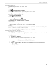
... the options list. 3. Set up the Test Tool: a. Push to short circuit the Input A and the Input B shielded banana sockets of the display). Industrial ScopeMeter Performance Verification Input A and Input B Tests To verify a measurement, choose items from a menu: 1. The Test Tool is off ) shows on Input B. Push the B button...
... the options list. 3. Set up the Test Tool: a. Push to short circuit the Input A and the Input B shielded banana sockets of the display). Industrial ScopeMeter Performance Verification Input A and Input B Tests To verify a measurement, choose items from a menu: 1. The Test Tool is off ) shows on Input B. Push the B button...

Calibration Guide
Page 23
... Calibrator Scope Output 50 Ω 2. b. Push . 4. b. On the Calibrator, supply a 25 MHz (123B) or 40 MHz (124B/125B) leveled sine wave of 1.8 V peak-to the Calibrator. If it is triggered. On the Calibrator, supply a 40 MHz (123B) or 60 ...A sensitivity on the display. Test Tool Input A to 4 divisions. Adjust the amplitude of the top row on 200 mV/div. 3. b. A B BNC Industrial ScopeMeter Performance Verification 5522A CALIBRATOR BB120 50Ω BNC Figure 3. The trigger icon () indicates the trigger level. 5. b. Push or ...
... Calibrator Scope Output 50 Ω 2. b. Push . 4. b. On the Calibrator, supply a 25 MHz (123B) or 40 MHz (124B/125B) leveled sine wave of 1.8 V peak-to the Calibrator. If it is triggered. On the Calibrator, supply a 40 MHz (123B) or 60 ...A sensitivity on the display. Test Tool Input A to 4 divisions. Adjust the amplitude of the top row on 200 mV/div. 3. b. A B BNC Industrial ScopeMeter Performance Verification 5522A CALIBRATOR BB120 50Ω BNC Figure 3. The trigger icon () indicates the trigger level. 5. b. Push or ...

Calibration Guide
Page 25
... the Calibrator: a. c. Push twice to Calibrator Scope Output 50 Ω 2. b. Compare the Input B main reading on the Test Tool with 1 MHz. b. Select Hz. A B BNC Industrial ScopeMeter Performance Verification 5522A CALIBRATOR BB120 50Ω BNC Figure 4. d. Make these selections: • Trigger Input: B • Update: Free Run • Type: Normal • Waveform...
... the Calibrator: a. c. Push twice to Calibrator Scope Output 50 Ω 2. b. Compare the Input B main reading on the Test Tool with 1 MHz. b. Select Hz. A B BNC Industrial ScopeMeter Performance Verification 5522A CALIBRATOR BB120 50Ω BNC Figure 4. d. Make these selections: • Trigger Input: B • Update: Free Run • Type: Normal • Waveform...

Calibration Guide
Page 27
... Trigger Level adjustment. Adjust the amplitude of the trigger icon (). On the Calibrator, supply a 40 MHz (123B) or 60 MHz (124B/125B) leveled sine wave of the sine wave to Calibrator Scope Output 19 See Figure 5. b. Push and then . 2....not, press to enable for positive or negative slope triggering: 1. If it is well triggered. a. Industrial ScopeMeter Performance Verification 4. If it is triggered. 7. Adjust the amplitude of the trigger icon (). Verify that the signal is well triggered.
... Trigger Level adjustment. Adjust the amplitude of the trigger icon (). On the Calibrator, supply a 40 MHz (123B) or 60 MHz (124B/125B) leveled sine wave of the sine wave to Calibrator Scope Output 19 See Figure 5. b. Push and then . 2....not, press to enable for positive or negative slope triggering: 1. If it is well triggered. a. Industrial ScopeMeter Performance Verification 4. If it is triggered. 7. Adjust the amplitude of the trigger icon (). Verify that the signal is well triggered.

Calibration Guide
Page 29
... step 15. 20. If traces show on the Calibrator to +1 divisions. Use to set the trigger level to reset the Test Tool. 26. Industrial ScopeMeter Performance Verification 16. Use the EDIT FIELD function on the display. 18. Set the Calibrator to slowly increase the voltage in 0.1 V steps until the...
... step 15. 20. If traces show on the Calibrator to +1 divisions. Use to set the trigger level to reset the Test Tool. 26. Industrial ScopeMeter Performance Verification 16. Use the EDIT FIELD function on the display. 18. Set the Calibrator to slowly increase the voltage in 0.1 V steps until the...

Calibration Guide
Page 31
... second column. For each sensitivity value listed in Table 4. 8. Push . On the Test Tool, push or to the limits in Table 4: a. Table 4. Industrial ScopeMeter Performance Verification d. f. Set up the Calibrator: i. Compare the main reading to set the Input A and Input B sensitivity. The range is tested in Table 4. b. ii.
... second column. For each sensitivity value listed in Table 4. 8. Push . On the Test Tool, push or to the limits in Table 4: a. Table 4. Industrial ScopeMeter Performance Verification d. f. Set up the Calibrator: i. Compare the main reading to set the Input A and Input B sensitivity. The range is tested in Table 4. b. ii.

Calibration Guide
Page 33
... Calibrator. Set up the Test Tool: a. Push . Setup Peak for Input A on the calibration source and connecting cables during the following steps. c. d. b. c. Push . Industrial ScopeMeter Performance Verification Input A and Input B AC Input Coupling Test To test the Input A and B ac input coupling: 1. Push to open the INPUT SETTINGS...
... Calibrator. Set up the Test Tool: a. Push . Setup Peak for Input A on the calibration source and connecting cables during the following steps. c. d. b. c. Push . Industrial ScopeMeter Performance Verification Input A and Input B AC Input Coupling Test To test the Input A and B ac input coupling: 1. Push to open the INPUT SETTINGS...

Calibration Guide
Page 35
...). Push . 27 d. c. Table 8. Push to the Calibrator. c. f. e. Set up the CalibratorCalibrator: a. Push . Setup the Test Tool: a. b. Supply a sine wave. Select Phase. d. Industrial ScopeMeter Performance Verification Input A and B Phase Measurements Test To test the Input A and B phase measurements: 1. Connect the Test Tool to highlight POWER HARMONICS. h. Select SENSITIVITY...
...). Push . 27 d. c. Table 8. Push to the Calibrator. c. f. e. Set up the CalibratorCalibrator: a. Push . Setup the Test Tool: a. b. Supply a sine wave. Select Phase. d. Industrial ScopeMeter Performance Verification Input A and B Phase Measurements Test To test the Input A and B phase measurements: 1. Connect the Test Tool to highlight POWER HARMONICS. h. Select SENSITIVITY...

Calibration Guide
Page 37
... the Calibrator: i. m. Supply the AC voltage (NORMAL output, WAVE sine) listed in Table 9. b. Note For this procedure, do not push . Select V ac. Push . Industrial ScopeMeter Performance Verification 2. k.
... the Calibrator: i. m. Supply the AC voltage (NORMAL output, WAVE sine) listed in Table 9. b. Note For this procedure, do not push . Select V ac. Push . Industrial ScopeMeter Performance Verification 2. k.

Calibration Guide
Page 39
.... Supply 25 Ω b. b. Push to the limit listed in Table 11: a. Compare the Input A main reading to open the INPUT A MEASUREMENTS menu. Supply 1 kΩ. Industrial ScopeMeter Performance Verification 3. Make sure the beeper sounds continuously. 5. Push . On the Calibrator, supply 1 V DC. 6. Use the "COMP 2 wire" mode. Connect the Test Tool...
.... Supply 25 Ω b. b. Push to the limit listed in Table 11: a. Compare the Input A main reading to open the INPUT A MEASUREMENTS menu. Supply 1 kΩ. Industrial ScopeMeter Performance Verification 3. Make sure the beeper sounds continuously. 5. Push . On the Calibrator, supply 1 V DC. 6. Use the "COMP 2 wire" mode. Connect the Test Tool...
Calibration Guide
Page 41
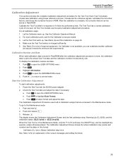
... its status in the Maintenance Mode, only the F1 to F4 soft keys, the ON/OFF key, and the backlight key operate, unless otherwise stated. Industrial ScopeMeter Calibration Adjustment Calibration Adjustment This section provides the complete Calibration Adjustment procedure for the Calibrator to become stable. 3. Start the Calibration Adjustment To start...
... its status in the Maintenance Mode, only the F1 to F4 soft keys, the ON/OFF key, and the backlight key operate, unless otherwise stated. Industrial ScopeMeter Calibration Adjustment Calibration Adjustment This section provides the complete Calibration Adjustment procedure for the Calibrator to become stable. 3. Start the Calibration Adjustment To start...

Calibration Guide
Page 43
... B is as short as the calibration status on the display. Supply a 1 kHz fast rising edge square wave (Output SCOPE, MODE edge). b. c. A B BB120 50Ω BNC Industrial ScopeMeter Calibration Adjustment 5522A CALIBRATOR BB120 PM9093/001 PM9091/001 (1.5 m) PM9092/001 (0.5 m) Figure 10. HF Gain Calibration Input Connections 3. Set up the Calibrator: a. On the...
... B is as short as the calibration status on the display. Supply a 1 kHz fast rising edge square wave (Output SCOPE, MODE edge). b. c. A B BB120 50Ω BNC Industrial ScopeMeter Calibration Adjustment 5522A CALIBRATOR BB120 PM9093/001 PM9091/001 (1.5 m) PM9092/001 (0.5 m) Figure 10. HF Gain Calibration Input Connections 3. Set up the Calibrator: a. On the...

Calibration Guide
Page 45
... present on the calibration source and connecting cables during the following steps. Connect the Test Tool to select the first Calibration Step in Table 15. 2. Industrial ScopeMeter Calibration Adjustment Gain DMM (Gain Volt) XW Warning To prevent possible electrical shock, fire, or personal injury, make sure that the calibrator is in...
... present on the calibration source and connecting cables during the following steps. Connect the Test Tool to select the first Calibration Step in Table 15. 2. Industrial ScopeMeter Calibration Adjustment Gain DMM (Gain Volt) XW Warning To prevent possible electrical shock, fire, or personal injury, make sure that the calibrator is in...
