Calibration Guide
Page 1
All product names are subject to change without notice. Specifications are trademarks of their respective companies. 123B/124B/125B Industrial ScopeMeter Calibration Manual May 2016 ©2016 Fluke Corporation. All rights reserved.
All product names are subject to change without notice. Specifications are trademarks of their respective companies. 123B/124B/125B Industrial ScopeMeter Calibration Manual May 2016 ©2016 Fluke Corporation. All rights reserved.
Calibration Guide
Page 9
This manual provides all the information necessary to the 123B/124B/125B Industrial ScopeMeter Users Manual at www.fluke.com. How to Contact Fluke To contact Fluke, call one easy-to do so. XW Warning To prevent electric shock or personal injury, do not perform the...instructions, refer to perform basic maintenance and make calibration adjustments. Introduction The 123B/124B/125B ScopeMeter® (the Test Tool or Product) is for the use instrument. To register your product, visit http://register.fluke.com. To view, print, or download the latest manual supplement, visit http...
This manual provides all the information necessary to the 123B/124B/125B Industrial ScopeMeter Users Manual at www.fluke.com. How to Contact Fluke To contact Fluke, call one easy-to do so. XW Warning To prevent electric shock or personal injury, do not perform the...instructions, refer to perform basic maintenance and make calibration adjustments. Introduction The 123B/124B/125B ScopeMeter® (the Test Tool or Product) is for the use instrument. To register your product, visit http://register.fluke.com. To view, print, or download the latest manual supplement, visit http...
Calibration Guide
Page 11
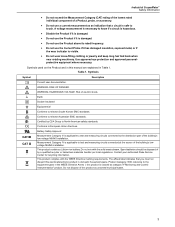
...complies with the solid waste stream. The affixed label indicates that a circuit is classed as unsorted municipal waste. 3 Industrial ScopeMeter Safety Information • Do not exceed the Measurement Category (CAT) rating of the lowest rated individual component of a... to test and measuring circuits connected at the source of electric shock. This product contains a Lithium-ion battery. Contact your authorized Fluke Service Center for recycling information. Table 1. HAZARDOUS VOLTAGE. Conforms to touch. A voltage measurement is necessary to North American safety standards...
...complies with the solid waste stream. The affixed label indicates that a circuit is classed as unsorted municipal waste. 3 Industrial ScopeMeter Safety Information • Do not exceed the Measurement Category (CAT) rating of the lowest rated individual component of a... to test and measuring circuits connected at the source of electric shock. This product contains a Lithium-ion battery. Contact your authorized Fluke Service Center for recycling information. Table 1. HAZARDOUS VOLTAGE. Conforms to touch. A voltage measurement is necessary to North American safety standards...
Calibration Guide
Page 13
... Trigger Source A, B Sensitivity A and B @ DC to 5 MHz 0.5 divisions or 5 mV @ 40 MHz 125B, 124B 1.5 divisions 123B 4 divisions @ 60 MHz 125B, 124B 4 divisions 123B NA Slope Positive, Negative Advanced Scope Functions Display Modes Normal Captures up to 25 ns glitches and displays analog-...25 counts) 5 MHz to 12.5 MHz 30 % + 25 counts) 5 MHz to 20 MHz (without test leads or probes 30 % + 25 counts) 5 Industrial ScopeMeter Specifications Time Base Accuracy Equivalent sampling 0.4 % + 0.025 time/div) Real time sampling 0.1 % + 0.025 time/div) Glitch Detection 25 ns @ 20 ns ...
... Trigger Source A, B Sensitivity A and B @ DC to 5 MHz 0.5 divisions or 5 mV @ 40 MHz 125B, 124B 1.5 divisions 123B 4 divisions @ 60 MHz 125B, 124B 4 divisions 123B NA Slope Positive, Negative Advanced Scope Functions Display Modes Normal Captures up to 25 ns glitches and displays analog-...25 counts) 5 MHz to 12.5 MHz 30 % + 25 counts) 5 MHz to 20 MHz (without test leads or probes 30 % + 25 counts) 5 Industrial ScopeMeter Specifications Time Base Accuracy Equivalent sampling 0.4 % + 0.025 time/div) Real time sampling 0.1 % + 0.025 time/div) Glitch Detection 25 ns @ 20 ns ...

Calibration Guide
Page 15
Industrial ScopeMeter Specifications with iFlex clamp Ranges 20 A/division Maximum Current 75 A @ 40 Hz to 300 Hz Frequency derating: I * F
Industrial ScopeMeter Specifications with iFlex clamp Ranges 20 A/division Maximum Current 75 A @ 40 Hz to 300 Hz Frequency derating: I * F

Calibration Guide
Page 17
...as Chart recorder display that plots a graph of min and max values of events 64 events on optional SD card (with the 125B or 124B). Industrial ScopeMeter Specifications Recorder The recorder captures meter readings in Meter Recorder mode or continuously captures waveform samples in Amp and Watt 10 % Field Bus.../s Record Size Internal memory 400 M samples Recorded Time Span internal memory 15 minutes at 500 μs/div 11 hours at 20 ms/div 125B, 124B Record Size SD card 15 G samples Recorded Time Span SD card 11 hours at 500 μs/div 14 days at 20 ms/div Maximum number...
...as Chart recorder display that plots a graph of min and max values of events 64 events on optional SD card (with the 125B or 124B). Industrial ScopeMeter Specifications Recorder The recorder captures meter readings in Meter Recorder mode or continuously captures waveform samples in Amp and Watt 10 % Field Bus.../s Record Size Internal memory 400 M samples Recorded Time Span internal memory 15 minutes at 500 μs/div 11 hours at 20 ms/div 125B, 124B Record Size SD card 15 G samples Recorded Time Span SD card 11 hours at 500 μs/div 14 days at 20 ms/div Maximum number...

Calibration Guide
Page 18
... to PC/laptop Transfer screen dumps (bitmaps), settings and data using OC4USB optically isolated USB adapter/cable, (optional), using FlukeView® ScopeMeter® software for Windows®. Environmental Environmental MIL-PRF-28800F, Class 2 Temperature Operating and charging 0 °C to 40 °C... °C (-4 °F to PC/laptop, tablet, smartphone, etc. A USB port is provided for attaching the WiFi Adapter. 123B/124B/125B Calibration Manual Miscellaneous Display Type 5.7-inch color active matrix TFT Resolution 640 pixels x 480 pixels Waveform Display Vertical 10 div of 40 ...
... to PC/laptop Transfer screen dumps (bitmaps), settings and data using OC4USB optically isolated USB adapter/cable, (optional), using FlukeView® ScopeMeter® software for Windows®. Environmental Environmental MIL-PRF-28800F, Class 2 Temperature Operating and charging 0 °C to 40 °C... °C (-4 °F to PC/laptop, tablet, smartphone, etc. A USB port is provided for attaching the WiFi Adapter. 123B/124B/125B Calibration Manual Miscellaneous Display Type 5.7-inch color active matrix TFT Resolution 640 pixels x 480 pixels Waveform Display Vertical 10 div of 40 ...

Calibration Guide
Page 19
... 2 Measurement IEC 61010-2-033: CAT IV 600 V / CAT III 750 V Max. USA (FCC 47 CFR 15 subpart B. Max. Industrial ScopeMeter Specifications Electromagnetic Compatibility (EMC) International IEC 61326-1: Industrial CISPR 11: Group 1, Class A Group 1: Equipment has intentionally generated and/or uses...103. This product is necessary for domestic purposes. Voltage Between Test Tool and STL120-IV Reference and Earth Ground The Fluke 12xB series, including standard accessories, conforms to conducted and radiated disturbances. Emissions that exceed the levels required by CISPR 11...
... 2 Measurement IEC 61010-2-033: CAT IV 600 V / CAT III 750 V Max. USA (FCC 47 CFR 15 subpart B. Max. Industrial ScopeMeter Specifications Electromagnetic Compatibility (EMC) International IEC 61326-1: Industrial CISPR 11: Group 1, Class A Group 1: Equipment has intentionally generated and/or uses...103. This product is necessary for domestic purposes. Voltage Between Test Tool and STL120-IV Reference and Earth Ground The Fluke 12xB series, including standard accessories, conforms to conducted and radiated disturbances. Emissions that exceed the levels required by CISPR 11...
Calibration Guide
Page 21
...; Noise filter: ON 13 In auto ranging mode, Auto shows on the display. 2. Set up the Test Tool: a. Select Factory Default and push . Industrial ScopeMeter Performance Verification Input A and Input B Tests To verify a measurement, choose items from a menu: 1. To choose an item from the menus. Push to turn...
...; Noise filter: ON 13 In auto ranging mode, Auto shows on the display. 2. Set up the Test Tool: a. Select Factory Default and push . Industrial ScopeMeter Performance Verification Input A and Input B Tests To verify a measurement, choose items from a menu: 1. To choose an item from the menus. Push to turn...

Calibration Guide
Page 23
A B BNC Industrial ScopeMeter Performance Verification 5522A CALIBRATOR BB120 50Ω BNC Figure 3. Set up the Calibrator: a. b. Verify that the signal is triggered. 7. On the Calibrator, supply a 25 MHz (123B) or 40 MHz (124B/125B) leveled sine wave of the sine wave to 4 divisions. If it is well ... 2. See Figure 3. b. The trigger icon () indicates the trigger level. 5. On the Calibrator, supply a 40 MHz (123B) or 60 MHz (124B/125B) leveled sine wave of the top row on 200 mV/div. 3. Push if AUTO does not show in the center of 1.8 V peak-...
A B BNC Industrial ScopeMeter Performance Verification 5522A CALIBRATOR BB120 50Ω BNC Figure 3. Set up the Calibrator: a. b. Verify that the signal is triggered. 7. On the Calibrator, supply a 25 MHz (123B) or 40 MHz (124B/125B) leveled sine wave of the sine wave to 4 divisions. If it is well ... 2. See Figure 3. b. The trigger icon () indicates the trigger level. 5. On the Calibrator, supply a 40 MHz (123B) or 60 MHz (124B/125B) leveled sine wave of the top row on 200 mV/div. 3. Push if AUTO does not show in the center of 1.8 V peak-...

Calibration Guide
Page 25
... 4. c. d. Push twice to -peak (SCOPE output, MODE levsine). Set up the Test Tool: a. b. Push to open the SCOPE SETTINGS menu. A B BNC Industrial ScopeMeter Performance Verification 5522A CALIBRATOR BB120 50Ω BNC Figure 4. b. Push . Push to Calibrator Scope Output 50 Ω 2. Connect the Test Tool...
... 4. c. d. Push twice to -peak (SCOPE output, MODE levsine). Set up the Test Tool: a. b. Push to open the SCOPE SETTINGS menu. A B BNC Industrial ScopeMeter Performance Verification 5522A CALIBRATOR BB120 50Ω BNC Figure 4. b. Push . Push to Calibrator Scope Output 50 Ω 2. Connect the Test Tool...

Calibration Guide
Page 27
... Tool to adjust the trigger level and verify that the signal is well triggered. On the Calibrator, supply a 40 MHz (123B) or 60 MHz (124B/125B) leveled sine wave of 1.8 V peak-to -peak. 6. Verify that the signal is triggered. 7. On the Calibrator, supply a 25 MHz (123B... To set the trigger level to adjust the trigger level and verify that the signal is not, press to exactly 4 divisions. Industrial ScopeMeter Performance Verification 4. Verify that the signal is the bottom of the sine wave to select positive slope triggering (trigger icon ) or ...
... Tool to adjust the trigger level and verify that the signal is well triggered. On the Calibrator, supply a 40 MHz (123B) or 60 MHz (124B/125B) leveled sine wave of 1.8 V peak-to -peak. 6. Verify that the signal is triggered. 7. On the Calibrator, supply a 25 MHz (123B... To set the trigger level to adjust the trigger level and verify that the signal is not, press to exactly 4 divisions. Industrial ScopeMeter Performance Verification 4. Verify that the signal is the bottom of the sine wave to select positive slope triggering (trigger icon ) or ...

Calibration Guide
Page 29
Industrial ScopeMeter Performance Verification 16. Verify that traces do not show on the display of the Test Tool and that the voltage on the status line ...
Industrial ScopeMeter Performance Verification 16. Verify that traces do not show on the display of the Test Tool and that the voltage on the status line ...

Calibration Guide
Page 31
... A and Input B sensitivity. Push . Push to open the INPUT SETTINGS A menu. Set up the Calibrator: i. Source the DC voltage listed in Table 4: a. Industrial ScopeMeter Performance Verification d. e. g. Volts DC Measurement Verification Points Sensitivity (Oscilloscope) Range[1] (Meter) Calibrator Output V DC 5 mV/div 500 mV 15 mV 10 mV/div 500...
... A and Input B sensitivity. Push . Push to open the INPUT SETTINGS A menu. Set up the Calibrator: i. Source the DC voltage listed in Table 4: a. Industrial ScopeMeter Performance Verification d. e. g. Volts DC Measurement Verification Points Sensitivity (Oscilloscope) Range[1] (Meter) Calibrator Output V DC 5 mV/div 500 mV 15 mV 10 mV/div 500...

Calibration Guide
Page 33
... to open the INPUT SETTINGS A menu and make sure that the calibrator is in Table 6. Compare the Test Tool reading to the Calibrator. Industrial ScopeMeter Performance Verification Input A and Input B AC Input Coupling Test To test the Input A and B ac input coupling: 1. Connect the Test Tool to the limit...
... to open the INPUT SETTINGS A menu and make sure that the calibrator is in Table 6. Compare the Test Tool reading to the Calibrator. Industrial ScopeMeter Performance Verification Input A and Input B AC Input Coupling Test To test the Input A and B ac input coupling: 1. Connect the Test Tool to the limit...

Calibration Guide
Page 35
... reading to highlight POWER HARMONICS. b. Push to the limit in Table 8 (NORMAL output, WAVE sine). Select Probe B: Select. e. Push . 3. See Figure 6. 2. d. Industrial ScopeMeter Performance Verification Input A and B Phase Measurements Test To test the Input A and B phase measurements: 1. Set up the CalibratorCalibrator: a. b. f. h. Set up the Calibrator: a. Push ...
... reading to highlight POWER HARMONICS. b. Push to the limit in Table 8 (NORMAL output, WAVE sine). Select Probe B: Select. e. Push . 3. See Figure 6. 2. d. Industrial ScopeMeter Performance Verification Input A and B Phase Measurements Test To test the Input A and B phase measurements: 1. Set up the CalibratorCalibrator: a. b. f. h. Set up the Calibrator: a. Push ...

Calibration Guide
Page 37
... Main (DC) Reading A-B -000.5 to +000.5 +497.0 to +503.0 -497.0 to -503.0 Secondary (AC) Reading A-B 494.0 to 506.0 486.0 to switch between moving A or B. 6. Industrial ScopeMeter Performance Verification 2. d. Push . Push to open the INPUT A MEASUREMENTS menu. j. The range is the secondary reading. 3. f. Select V dc. V dc becomes the main...
... Main (DC) Reading A-B -000.5 to +000.5 +497.0 to +503.0 -497.0 to -503.0 Secondary (AC) Reading A-B 494.0 to 506.0 486.0 to switch between moving A or B. 6. Industrial ScopeMeter Performance Verification 2. d. Push . Push to open the INPUT A MEASUREMENTS menu. j. The range is the secondary reading. 3. f. Select V dc. V dc becomes the main...

Calibration Guide
Page 39
...; to open the INPUT A MEASUREMENTS menu. c. Connect the Test Tool to the Calibrator. c. Select CAP. 3. For each Range and Output value in Table 11. Industrial ScopeMeter Performance Verification 3. Supply 25 Ω b. Make sure the beeper sounds continuously. 5. Connect the Test Tool to the Calibrator. Push . Verify the main reading...
...; to open the INPUT A MEASUREMENTS menu. c. Connect the Test Tool to the Calibrator. c. Select CAP. 3. For each Range and Output value in Table 11. Industrial ScopeMeter Performance Verification 3. Supply 25 Ω b. Make sure the beeper sounds continuously. 5. Connect the Test Tool to the Calibrator. Push . Verify the main reading...
Calibration Guide
Page 41
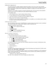
.... Each Test Tool allows closed-case calibration using known reference sources. See the Calibrator Operators Manual. 2. Start the Calibration Adjustment To start calibration adjustments: 1. Industrial ScopeMeter Calibration Adjustment Calibration Adjustment This section provides the complete Calibration Adjustment procedure for an explanation of required equipment. If a Calibrator is not available, you...
.... Each Test Tool allows closed-case calibration using known reference sources. See the Calibrator Operators Manual. 2. Start the Calibration Adjustment To start calibration adjustments: 1. Industrial ScopeMeter Calibration Adjustment Calibration Adjustment This section provides the complete Calibration Adjustment procedure for an explanation of required equipment. If a Calibrator is not available, you...

Calibration Guide
Page 43
A B BB120 50Ω BNC Industrial ScopeMeter Calibration Adjustment 5522A CALIBRATOR BB120 PM9093/001 PM9091/001 (1.5 m) PM9092/001 (0.5 m) Figure 10. b. On the Test Tool: a. b. HF Gain Calibration Points Fast Calibration Step ...
A B BB120 50Ω BNC Industrial ScopeMeter Calibration Adjustment 5522A CALIBRATOR BB120 PM9093/001 PM9091/001 (1.5 m) PM9092/001 (0.5 m) Figure 10. b. On the Test Tool: a. b. HF Gain Calibration Points Fast Calibration Step ...
