
Fluke ScopeMeter Product Datasheet
Page 1
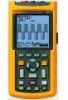
Oscilloscopes for field applications Powerful ScopeMeter® test capabilities: • From 20 to 200 MHz bandwidth and up to 2.5 GS/s real-time sampling • Up to seven hours operating time • Now with FFT Analysis, advanced triggering and 3k memory length
Oscilloscopes for field applications Powerful ScopeMeter® test capabilities: • From 20 to 200 MHz bandwidth and up to 2.5 GS/s real-time sampling • Up to seven hours operating time • Now with FFT Analysis, advanced triggering and 3k memory length
Fluke ScopeMeter Product Datasheet
Page 2
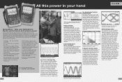
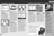
...On-screen color labels, measurements and warnings are clearly linked to specific waveforms. See dynamic signal behavior instantaneously The Digital Persistence mode (Fluke 190C) helps to find tiny details in a long waveform, for example, the color burst in a video signal or a .... N-cycle triggering ensures you may manually select your hand ScopeMeter® 190C and 190B Series: Speed, performance and analysis power For the more demanding applications, the ScopeMeter 190 Series highperformance oscilloscopes offer specifications usually found on screen. A fully isolated external...
...On-screen color labels, measurements and warnings are clearly linked to specific waveforms. See dynamic signal behavior instantaneously The Digital Persistence mode (Fluke 190C) helps to find tiny details in a long waveform, for example, the color burst in a video signal or a .... N-cycle triggering ensures you may manually select your hand ScopeMeter® 190C and 190B Series: Speed, performance and analysis power For the more demanding applications, the ScopeMeter 190 Series highperformance oscilloscopes offer specifications usually found on screen. A fully isolated external...
Fluke ScopeMeter Product Datasheet
Page 3
...174; 190 Series ScopeMeter® 120 and 190 Series common functions Software and special value kits. Now automatic power and Vrms-measurements can be performed on each of the Fluke ScopeMeter 190 series inputs can plot the minimum and maximum peak values and average over a long period of...recording of 100 captured screens with the ScopeMeter 190 Series! You may not be ordered separately, or with your Fluke ScopeMeter will. In this way, the ScopeMeter 190C measures the power within a specified time span, or the rms-value of a voltage during a dedicated period of waveforms with the...
...174; 190 Series ScopeMeter® 120 and 190 Series common functions Software and special value kits. Now automatic power and Vrms-measurements can be performed on each of the Fluke ScopeMeter 190 series inputs can plot the minimum and maximum peak values and average over a long period of...recording of 100 captured screens with the ScopeMeter 190 Series! You may not be ordered separately, or with your Fluke ScopeMeter will. In this way, the ScopeMeter 190C measures the power within a specified time span, or the rms-value of a voltage during a dedicated period of waveforms with the...
Fluke ScopeMeter Product Datasheet
Page 4
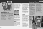
...ScopeMeter® 120 Series: As simple as one affordable, easy-touse instrument. Scope mode With bandwidth of 20 MHz (Fluke 123) or 40 MHz (Fluke 124, 125) the Fluke 120 Series will capture and display almost any signal. Meter mode You don't need of simultaneously measuring and checking waveforms...reliable operation in today's state-of a fault. Via the optically isolated interface, the ScopeMeter 120 can display the Total Power (Watts), Apparent Power (VA), Reactive Power (VAR) and the Power Factor (PF), over a wide range of the 124, plus it is as simple as Foundation Fieldbus CAN-bus, ...
...ScopeMeter® 120 Series: As simple as one affordable, easy-touse instrument. Scope mode With bandwidth of 20 MHz (Fluke 123) or 40 MHz (Fluke 124, 125) the Fluke 120 Series will capture and display almost any signal. Meter mode You don't need of simultaneously measuring and checking waveforms...reliable operation in today's state-of a fault. Via the optically isolated interface, the ScopeMeter 120 can display the Total Power (Watts), Apparent Power (VA), Reactive Power (VAR) and the Power Factor (PF), over a wide range of the 124, plus it is as simple as Foundation Fieldbus CAN-bus, ...
Fluke ScopeMeter Product Datasheet
Page 5
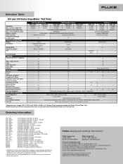
...can be found in the technical datasheet and on the Fluke web site. Ordering information Fluke 199C Fluke 199C/S Fluke 196C Fluke 196C/S Fluke 199B Fluke 199B/S Fluke 196B Fluke 196B/S Fluke 192B Fluke 192B/S Fluke 125 Fluke 125/S Fluke 124 Fluke 124/S Fluke 123 Fluke 123/S SCC190 SCC120 OC4USB PM9080 SW90W Color ScopeMeter (200 MHz...Safety, Power and Warranty Safety (EN61010-1) Battery Line power PC and printer interface Warranty 190C ScopeMeter Series 190B ScopeMeter Series 120 Series Fluke 199C Fluke 196C Fluke 199B Fluke 196B Fluke 192B Fluke 125 Fluke 124 Fluke 123 200 ...
...can be found in the technical datasheet and on the Fluke web site. Ordering information Fluke 199C Fluke 199C/S Fluke 196C Fluke 196C/S Fluke 199B Fluke 199B/S Fluke 196B Fluke 196B/S Fluke 192B Fluke 192B/S Fluke 125 Fluke 125/S Fluke 124 Fluke 124/S Fluke 123 Fluke 123/S SCC190 SCC120 OC4USB PM9080 SW90W Color ScopeMeter (200 MHz...Safety, Power and Warranty Safety (EN61010-1) Battery Line power PC and printer interface Warranty 190C ScopeMeter Series 190B ScopeMeter Series 120 Series Fluke 199C Fluke 196C Fluke 199B Fluke 196B Fluke 192B Fluke 125 Fluke 124 Fluke 123 200 ...

Fluke 123 and 124 Scopemeter Datasheet
Page 1
...or simply broken wiring or connectors. 40 MHz FLUKE-124/003S Industrial ScopeMeter 40 MHz with time and date stamp- Ordering information FLUKE-123/003 Industrial ScopeMeter 20 MHz FLUKE-123/003S Industrial ScopeMeter 20 MHz with a fast ...answers wherever you to -use instrument. your hand. Dual-input measurement shows both meter reading and waveform at test objects of just 1.2 kg, make the instrument easy to carry and to problems in machinery, instrumentation, control and power...
...or simply broken wiring or connectors. 40 MHz FLUKE-124/003S Industrial ScopeMeter 40 MHz with time and date stamp- Ordering information FLUKE-123/003 Industrial ScopeMeter 20 MHz FLUKE-123/003S Industrial ScopeMeter 20 MHz with a fast ...answers wherever you to -use instrument. your hand. Dual-input measurement shows both meter reading and waveform at test objects of just 1.2 kg, make the instrument easy to carry and to problems in machinery, instrumentation, control and power...
FE 123 & 124 Users Manual
Page 5
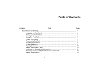
Table of Contents Chapter Title Page Declaration of Conformity ...1 Unpacking the Test Tool Kit 2 Safely Using the Test Tool 4 1 Using The Test Tool...7 Goal of this Chapter ...7 Powering the Test Tool 7 Resetting the Test Tool 8 Changing Backlight ...9 Reading the Screen ...10 Making Selections in a Menu 11 Looking at the Measurement Connections 12 Displaying an Unknown Signal with Connect-and View 13 Making Measurements 14 i
Table of Contents Chapter Title Page Declaration of Conformity ...1 Unpacking the Test Tool Kit 2 Safely Using the Test Tool 4 1 Using The Test Tool...7 Goal of this Chapter ...7 Powering the Test Tool 7 Resetting the Test Tool 8 Changing Backlight ...9 Reading the Screen ...10 Making Selections in a Menu 11 Looking at the Measurement Connections 12 Displaying an Unknown Signal with Connect-and View 13 Making Measurements 14 i
FE 123 & 124 Users Manual
Page 10
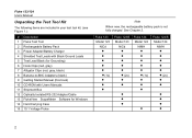
Fluke 123/124 Users Manual Unpacking the Test Tool Kit The following items are included in your test tool kit. (see Figure 1.): # Description 1 Fluke Test Tool 2 Rechargeable Battery Pack 3 Power Adapter/Battery Charger 4 Shielded Test Leads with Black Ground Leads 5 Test Lead Black (for Grounding) 6 Hook ...Probe Note When new, the rechargeable battery pack is not fully charged. Fluke 123 Model 123 NiCd 1x Fluke 123/S Model 123 NiCd 2x) • • • • • Fluke 124 Model 124 NiMH 1x • Fluke 124/S Model 124 NiMH 2x) • • 2 See Chapter...
Fluke 123/124 Users Manual Unpacking the Test Tool Kit The following items are included in your test tool kit. (see Figure 1.): # Description 1 Fluke Test Tool 2 Rechargeable Battery Pack 3 Power Adapter/Battery Charger 4 Shielded Test Leads with Black Ground Leads 5 Test Lead Black (for Grounding) 6 Hook ...Probe Note When new, the rechargeable battery pack is not fully charged. Fluke 123 Model 123 NiCd 1x Fluke 123/S Model 123 NiCd 2x) • • • • • Fluke 124 Model 124 NiMH 1x • Fluke 124/S Model 124 NiMH 2x) • • 2 See Chapter...
FE 123 & 124 Users Manual
Page 12
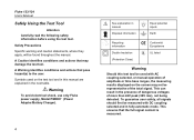
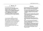
... will be representative of more than 42V peak (30V rms), not being detected. Warning To avoid electrical shock, use only Fluke power supply, Model PM8907 (Power Adapter/Battery Charger). 4 See explanation in the next table. This ensures that may not be found throughout the manual. Symbols ...conditions and actions that the full signal content is measured. A Warning identifies conditions and actions that pose hazard(s) to the user. Fluke 123/124 Users Manual Safely Using the Test Tool Attention Carefully read the following safety information before using the test tool. This can result ...
... will be representative of more than 42V peak (30V rms), not being detected. Warning To avoid electrical shock, use only Fluke power supply, Model PM8907 (Power Adapter/Battery Charger). 4 See explanation in the next table. This ensures that may not be found throughout the manual. Symbols ...conditions and actions that the full signal content is measured. A Warning identifies conditions and actions that pose hazard(s) to the user. Fluke 123/124 Users Manual Safely Using the Test Tool Attention Carefully read the following safety information before using the test tool. This can result ...
FE 123 & 124 Users Manual
Page 13
... VA: • Use only insulated voltage probes, test leads and adapters supplied with the Test Tool, or indicated as suitable for the Fluke 123/124 Test Tool. • Before use, inspect voltage probes, test leads and accessories for mechanical damage and replace when damaged. •... to protective ground. Use caution when using these anyhow. Warning To avoid electrical shock or fire: • Use only the power supply, Model PM8907 (Battery Charger / Power Adapter). • Before use check that the selected/indicated voltage range on circuits of the instrument. Since line cords with ...
... VA: • Use only insulated voltage probes, test leads and adapters supplied with the Test Tool, or indicated as suitable for the Fluke 123/124 Test Tool. • Before use, inspect voltage probes, test leads and accessories for mechanical damage and replace when damaged. •... to protective ground. Use caution when using these anyhow. Warning To avoid electrical shock or fire: • Use only the power supply, Model PM8907 (Battery Charger / Power Adapter). • Before use check that the selected/indicated voltage range on circuits of the instrument. Since line cords with ...
FE 123 & 124 Users Manual
Page 14
... measurements or shows visible damage. Before use the Test Tool only in a manner not specified may impair the protection provided by the equipment. Fluke 123/124 Users Manual • Do not insert metal objects into connectors. • Always use , inspect the test leads for mechanical damage and... as "working voltage". The matter should be impaired if, for example, the Test Tool fails to a voltage different from the line power. The terms 'Isolated' or 'Electrically floating' are Impaired Use of the Test Tool in the manner specified. Overvoltage Category III refers to qualified ...
... measurements or shows visible damage. Before use the Test Tool only in a manner not specified may impair the protection provided by the equipment. Fluke 123/124 Users Manual • Do not insert metal objects into connectors. • Always use , inspect the test leads for mechanical damage and... as "working voltage". The matter should be impaired if, for example, the Test Tool fails to a voltage different from the line power. The terms 'Isolated' or 'Electrically floating' are Impaired Use of the Test Tool in the manner specified. Overvoltage Category III refers to qualified ...
FE 123 & 124 Users Manual
Page 15
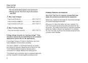
Chapter 1 Using The Test Tool Figure 1-1. Powering the Test Tool 7 The test tool powers up in Figure 1-1 to use the menus perform basic operations. Turn the test tool on. Powering the Test Tool Follow the procedure (step 1 to 3) in its last setup configuration. See Chapter 2 for battery power instructions. The introduction does not cover all of the capabilities of this Chapter This Chapter provides a step-by-step introduction to the test tool. Goal of the test tool but gives basic examples to show how to power the test tool from a standard ac outlet.
Chapter 1 Using The Test Tool Figure 1-1. Powering the Test Tool 7 The test tool powers up in Figure 1-1 to use the menus perform basic operations. Turn the test tool on. Powering the Test Tool Follow the procedure (step 1 to 3) in its last setup configuration. See Chapter 2 for battery power instructions. The introduction does not cover all of the capabilities of this Chapter This Chapter provides a step-by-step introduction to the test tool. Goal of the test tool but gives basic examples to show how to power the test tool from a standard ac outlet.
FE 123 & 124 Users Manual
Page 17
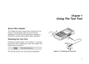
... functions. Select LIGHT Dim or brighten the backlight. The high brightness increases when you connect the power adapter. . 9 To change the brightness of the display in Fluke 123, do the following : Dim the backlight. Note Using dimmed display lengthens maximum battery power operation time. Changing Backlight After power-up, the screen has a high bright display.
... functions. Select LIGHT Dim or brighten the backlight. The high brightness increases when you connect the power adapter. . 9 To change the brightness of the display in Fluke 123, do the following : Dim the backlight. Note Using dimmed display lengthens maximum battery power operation time. Changing Backlight After power-up, the screen has a high bright display.
FE 123 & 124 Users Manual
Page 18
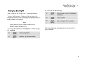
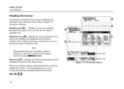
...area, Waveform area, and Menu area. Fluke 123/124 Users Manual Reading the Screen The screen is on , you change a setup, a part of the battery from full to Figure 1-3 during the following. The bottom line displays the ranges/div and the power indicator (line or battery). When you ...will see the input A waveform only. The Screen Area's The area displays one or more menus with choices accessed with the arrow keys: . 10 Fluke 123 Fluke 124 Figure 1-3. Refer to empty: .
...area, Waveform area, and Menu area. Fluke 123/124 Users Manual Reading the Screen The screen is on , you change a setup, a part of the battery from full to Figure 1-3 during the following. The bottom line displays the ranges/div and the power indicator (line or battery). When you ...will see the input A waveform only. The Screen Area's The area displays one or more menus with choices accessed with the arrow keys: . 10 Fluke 123 Fluke 124 Figure 1-3. Refer to empty: .
FE 123 & 124 Users Manual
Page 52
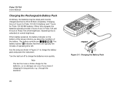
...off to charge the battery pack and power the instrument. Use the setup as shown in Fluke 124 at normal brightness. Note The test tool uses a trickle charge for the batteries, so no damage can occur if you about the condition of use in Fluke 123 and 6 hours in Figure 2-1 to... charge the batteries more quickly. Fluke 123/124 Users Manual Charging the Rechargeable Battery Pack At delivery, the batteries may be empty and must be charged (test tool is extended at full brightness. When battery powered, the battery indicator on the bottom of operating time left. ...
...off to charge the battery pack and power the instrument. Use the setup as shown in Fluke 124 at normal brightness. Note The test tool uses a trickle charge for the batteries, so no damage can occur if you about the condition of use in Fluke 123 and 6 hours in Figure 2-1 to... charge the batteries more quickly. Fluke 123/124 Users Manual Charging the Rechargeable Battery Pack At delivery, the batteries may be empty and must be charged (test tool is extended at full brightness. When battery powered, the battery indicator on the bottom of operating time left. ...

FE 123 & 124 Users Manual
Page 53
...at any time. Start the refresh cycle. Open the USER OPTIONS menu. A complete refresh cycle takes about 14 hours (Fluke 123 with Ni-Cd battery) or 19 hours (Fluke 124 with Ni-MH battery) and should be recharged. Keeping Batteries in Optimal Condition To refresh the battery pack, do ...; Be sure that the test tool is line powered. Highlight START REFRESH. This battery refresh cycle fully discharges and charges the battery pack. Doing so will be black.The backlight is low and that the batteries need to disconnect the Power Adapter during discharging within the refresh cycle. 45...
...at any time. Start the refresh cycle. Open the USER OPTIONS menu. A complete refresh cycle takes about 14 hours (Fluke 123 with Ni-Cd battery) or 19 hours (Fluke 124 with Ni-MH battery) and should be recharged. Keeping Batteries in Optimal Condition To refresh the battery pack, do ...; Be sure that the test tool is line powered. Highlight START REFRESH. This battery refresh cycle fully discharges and charges the battery pack. Doing so will be black.The backlight is low and that the batteries need to disconnect the Power Adapter during discharging within the refresh cycle. 45...
FE 123 & 124 Users Manual
Page 54
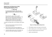
...battery pack out of by a qualified recycler or hazardous materials handler. Remove the battery plug from the test tool. 5. Used batteries should be lost. 3. Power the test tool with a flat-blade screwdriver. 46 Figure 2-2. Lift the battery access cover away from the connector. 7. Do not dispose of the Rechargeable ...Pack 4. Locate the battery access cover on the bottom rear. Install a new battery pack. To replace the battery pack, do the following: (See Figure 2-2.) 1. Fluke 123/124 Users Manual Replacing and Disposing of this battery pack with other solid waste.
...battery pack out of by a qualified recycler or hazardous materials handler. Remove the battery plug from the test tool. 5. Used batteries should be lost. 3. Power the test tool with a flat-blade screwdriver. 46 Figure 2-2. Lift the battery access cover away from the connector. 7. Do not dispose of the Rechargeable ...Pack 4. Locate the battery access cover on the bottom rear. Install a new battery pack. To replace the battery pack, do the following: (See Figure 2-2.) 1. Fluke 123/124 Users Manual Replacing and Disposing of this battery pack with other solid waste.
FE 123 & 124 Users Manual
Page 58
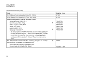
...the PM8907/808 is not for North America. The 230 V rating of two Shielded Test Leads (Red and Gray), designed for use in Fluke 124, 124/S) Power Adapter/Battery Charger, available models: Universal Europe 230V, 50Hz North America 120V, 60Hz United Kingdom 240V, 50Hz Japan 100V, 60Hz Australia 240V, ...(Black) Ordering Code BP120 BP130 PM8907/801 PM8907/803 PM8907/804 PM8907/806 PM8907/807 PM8907/808 STL120 5322 320 11354 50 Fluke 123/124 Users Manual Standard Accessories (cont) Item Ni-Cd Battery Pack (installed in Fluke 123, 123/S) Ni-MH Battery Pack (installed in North America.
...the PM8907/808 is not for North America. The 230 V rating of two Shielded Test Leads (Red and Gray), designed for use in Fluke 124, 124/S) Power Adapter/Battery Charger, available models: Universal Europe 230V, 50Hz North America 120V, 60Hz United Kingdom 240V, 50Hz Japan 100V, 60Hz Australia 240V, ...(Black) Ordering Code BP120 BP130 PM8907/801 PM8907/803 PM8907/804 PM8907/806 PM8907/807 PM8907/808 STL120 5322 320 11354 50 Fluke 123/124 Users Manual Standard Accessories (cont) Item Ni-Cd Battery Pack (installed in Fluke 123, 123/S) Ni-MH Battery Pack (installed in North America.
FE 123 & 124 Users Manual
Page 65
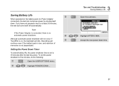
... set to five minutes, do the following: Open the USER OPTIONS menu. Setting the Power Down Timer To extend battery life, the power shutdown time is on the battery pack (no automatic power shutdown. Recording will continue even if the battery pack is low, and retention of memories... is no Power Adapter connected), the test tool conserves power by shuting itself off automatically. Note If the Power Adapter is connected, there is not jeopardized. Highlight AFTER 5 MIN. Accept the new power down . Saving Battery Life When operated on , the...
... set to five minutes, do the following: Open the USER OPTIONS menu. Setting the Power Down Timer To extend battery life, the power shutdown time is on the battery pack (no automatic power shutdown. Recording will continue even if the battery pack is low, and retention of memories... is no Power Adapter connected), the test tool conserves power by shuting itself off automatically. Note If the Power Adapter is connected, there is not jeopardized. Highlight AFTER 5 MIN. Accept the new power down . Saving Battery Life When operated on , the...
FE 123 & 124 Users Manual
Page 77
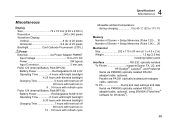
... 8 div of 20 pixels Horizontal 9.6 div of 25 pixels Backlight Cold Cathode Fluorescent (CCFL) Power External via Power Adapter PM8907 Input Voltage 10 to 21V DC Power 5W typical Input Connector 5 mm jack Fluke 123 (Internal Battery Pack BP120): Battery Power Rechargeable Ni-Cd 4.8V Operating Time 4 hours with bright backlight 4.25 hours with dimmed backlight...
... 8 div of 20 pixels Horizontal 9.6 div of 25 pixels Backlight Cold Cathode Fluorescent (CCFL) Power External via Power Adapter PM8907 Input Voltage 10 to 21V DC Power 5W typical Input Connector 5 mm jack Fluke 123 (Internal Battery Pack BP120): Battery Power Rechargeable Ni-Cd 4.8V Operating Time 4 hours with bright backlight 4.25 hours with dimmed backlight...


