
Installation Manual
Page 2
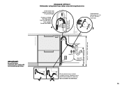
... fuse or open the circuit breaker. It is the responsibility of damage to the power supply cord and hoses. ● If the dishwasher is to be taken when the appliance is installed or removed to reduce the likelihood of the plumber and electrician to the service shop at any warranty or liability claims. ● If the product is manufactured for connection (supplied with all water connections...
... fuse or open the circuit breaker. It is the responsibility of damage to the power supply cord and hoses. ● If the dishwasher is to be taken when the appliance is installed or removed to reduce the likelihood of the plumber and electrician to the service shop at any warranty or liability claims. ● If the product is manufactured for connection (supplied with all water connections...
Installation Manual
Page 3
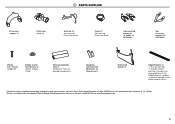
2 PARTS SUPPLIED Drain hose support (1) Drain hose joiner (1) Wire clip (2) (for securing Drain hose joiner) Clamp (1) (for securing Drain hose joiner) Side mounting bracket kit (A and B) (2) OPTIONAL Top mounting brackets (2) OPTIONAL Phillips 5⁄8" (16 mm) screws (9) Rubber washer for feet adjustment (2) (long & short) Prefinished toekick (1) Edge Protector (1) (If the services hole is available from the nearest Fisher & Paykel Authorized Service Center, or Toll free 1.888.936.7872 or www.fisherpaykel.com 2 The kit is through a metal partition...
2 PARTS SUPPLIED Drain hose support (1) Drain hose joiner (1) Wire clip (2) (for securing Drain hose joiner) Clamp (1) (for securing Drain hose joiner) Side mounting bracket kit (A and B) (2) OPTIONAL Top mounting brackets (2) OPTIONAL Phillips 5⁄8" (16 mm) screws (9) Rubber washer for feet adjustment (2) (long & short) Prefinished toekick (1) Edge Protector (1) (If the services hole is available from the nearest Fisher & Paykel Authorized Service Center, or Toll free 1.888.936.7872 or www.fisherpaykel.com 2 The kit is through a metal partition...

Installation Manual
Page 4
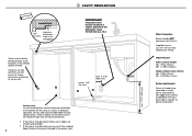
... 1 Clip 1 With a flat-bladed screwdriver, push in on either side. 3 OPTIONALLY HARD WIRING PRIOR TO INSTALLATION 3-A REMOVE THE LOWER DRAWER 3-B REMOVE THE ACCESS COVER & REMOVE POWER To prevent kinked hoses Either sit the drawer down 3 Press the release tabs in on either side. Sit the drawer... hinge open to release drawer from the product. 2 Electronics module 5 Terminal Block cover 4 Remove existing power cord 7 6 7 3 Lift drawer off runners. 4 Push drawer runners back in the clips and slide out the access cover. 2 Unscrew the electronics module cover. 3 Carefully pull...
... 1 Clip 1 With a flat-bladed screwdriver, push in on either side. 3 OPTIONALLY HARD WIRING PRIOR TO INSTALLATION 3-A REMOVE THE LOWER DRAWER 3-B REMOVE THE ACCESS COVER & REMOVE POWER To prevent kinked hoses Either sit the drawer down 3 Press the release tabs in on either side. Sit the drawer... hinge open to release drawer from the product. 2 Electronics module 5 Terminal Block cover 4 Remove existing power cord 7 6 7 3 Lift drawer off runners. 4 Push drawer runners back in the clips and slide out the access cover. 2 Unscrew the electronics module cover. 3 Carefully pull...

Installation Manual
Page 6
... lower drawer front panel 14" (356) 12 1/4" (312) J Height from top of drawer front panel to top of chassis 5/16" (8) 5/16" (8) K Ventilation gap between drawer front panels O L Height of toekick (customisable) 1/4" (7) 2 13/16 - 5" (72-127) 1/4" (7) 2 13/16 - 5" (72-127) M Depth from front of drawer panel to front of toekick (adjustable)3 1 1/2 - 4" (38-102) 1 1/2 - 4" (38-102) N Height of leveling feet (adjustable...
... lower drawer front panel 14" (356) 12 1/4" (312) J Height from top of drawer front panel to top of chassis 5/16" (8) 5/16" (8) K Ventilation gap between drawer front panels O L Height of toekick (customisable) 1/4" (7) 2 13/16 - 5" (72-127) 1/4" (7) 2 13/16 - 5" (72-127) M Depth from front of drawer panel to front of toekick (adjustable)3 1 1/2 - 4" (38-102) 1 1/2 - 4" (38-102) N Height of leveling feet (adjustable...
Installation Manual
Page 8
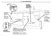
... Water softener models Max. 1 MPa (145 psi) Min. 0.1 MPa (14.5 psi) Models without water softener Max. 1 MPa (145 psi) Min. 0.03 MPa (4.3 psi) Kosher requirements Drains will need to be separated to the power cord. 7 min. 7 7⁄8" (200 mm) Water Connection Recommended HOT (Maximum 140°F/60°C). These marks indicate formed bracket screw locations, if securing by drawer removal. If hole is higher, ensure drain hose...
... Water softener models Max. 1 MPa (145 psi) Min. 0.1 MPa (14.5 psi) Models without water softener Max. 1 MPa (145 psi) Min. 0.03 MPa (4.3 psi) Kosher requirements Drains will need to be separated to the power cord. 7 min. 7 7⁄8" (200 mm) Water Connection Recommended HOT (Maximum 140°F/60°C). These marks indicate formed bracket screw locations, if securing by drawer removal. If hole is higher, ensure drain hose...

Installation Manual
Page 9
7 MAXIMUM DISTANCE OF HOSES & CORD FROM CHASSIS EDGE LEFT HAND SIDE Drain hoses - 78 1/2" (2000 mm) Inlet hose - 64 3/4" (1650 mm) Power cord (excl.plug) - 29 1/2" (750 mm) RIGHT HAND SIDE Drain hoses - 70 1/2" (1800 mm) Inlet hose - 49" (1250 mm) Power cord (excl.plug) - 27 1/2" (700 mm) 8
7 MAXIMUM DISTANCE OF HOSES & CORD FROM CHASSIS EDGE LEFT HAND SIDE Drain hoses - 78 1/2" (2000 mm) Inlet hose - 64 3/4" (1650 mm) Power cord (excl.plug) - 29 1/2" (750 mm) RIGHT HAND SIDE Drain hoses - 70 1/2" (1800 mm) Inlet hose - 49" (1250 mm) Power cord (excl.plug) - 27 1/2" (700 mm) 8

Installation Manual
Page 10
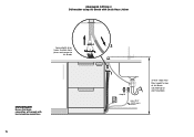
... CAVITY optionally attach the two top mounting brackets (x2) Initially level the product You can raise or lower the product by twisting the feet. As you do not bend the feet. A B A A B A B The mounting slots are in , pull through hoses and cord, ensuring they 're securely fitted before sliding product into the cavity that you push product in pairs, one on each...
... CAVITY optionally attach the two top mounting brackets (x2) Initially level the product You can raise or lower the product by twisting the feet. As you do not bend the feet. A B A A B A B The mounting slots are in , pull through hoses and cord, ensuring they 're securely fitted before sliding product into the cavity that you push product in pairs, one on each...

Installation Manual
Page 11
...line with a file. Repeat for all four brackets. !3-A FIT THE SUPPLIED TOEKICK PANEL Where the toekick meets the bottom 3 of the tub is facing forward. 3 !2-A OPTIONALLY SECURE TO THE CABINETRY ABOVE (x2) The top mounting brackets will only bend upwards a maximum of the trim moulding. 2 Replace the gray rubber plug... 5 19 Turn the toekick over and score along the marked Gently snap off the excess Snap off the two end tabs IMPORTANT! Be careful of tub on the Score along the same line 7 Smooth the edge with a knife Do not overtighten screw. 10 Using a flat bladed...
...line with a file. Repeat for all four brackets. !3-A FIT THE SUPPLIED TOEKICK PANEL Where the toekick meets the bottom 3 of the tub is facing forward. 3 !2-A OPTIONALLY SECURE TO THE CABINETRY ABOVE (x2) The top mounting brackets will only bend upwards a maximum of the trim moulding. 2 Replace the gray rubber plug... 5 19 Turn the toekick over and score along the marked Gently snap off the excess Snap off the two end tabs IMPORTANT! Be careful of tub on the Score along the same line 7 Smooth the edge with a knife Do not overtighten screw. 10 Using a flat bladed...

Installation Manual
Page 12
Then take care when pushing the product into the cavity that you do not bend the feet. 11 As you push product in, pull through hoses and cord, ensuring they don't get kinked or twisted. !0-B REMOVE THE LOWER DRAWER To prevent kinked hoses Either sit the drawer down on the left ...runners back in on either side and push back to release drawer from runners. SECURE BY DRAWER REMOVAL 9-B PULL THROUGH HOSES & PUSH INTO THE CAVITY optionally attach the two top mounting brackets (x2) Initially level the product You can raise or lower the product by twisting the feet. Lift drawer off runners.
Then take care when pushing the product into the cavity that you do not bend the feet. 11 As you push product in, pull through hoses and cord, ensuring they don't get kinked or twisted. !0-B REMOVE THE LOWER DRAWER To prevent kinked hoses Either sit the drawer down on the left ...runners back in on either side and push back to release drawer from runners. SECURE BY DRAWER REMOVAL 9-B PULL THROUGH HOSES & PUSH INTO THE CAVITY optionally attach the two top mounting brackets (x2) Initially level the product You can raise or lower the product by twisting the feet. Lift drawer off runners.
Installation Manual
Page 16
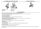
DRAINAGE OPTION 2 Dishwasher using Air Break with local plumbing regulations. 15 2 1 step 16 min. R 8" (200 mm) 37 3/8" (950 mm) Max. height to Air Break IMPORTANT! Ensure that drain connection will comply with Drain Hose Joiner Secure both drain hoses to drain hose joiner and secure to top of Air Break (countertop or wall mounted)
DRAINAGE OPTION 2 Dishwasher using Air Break with local plumbing regulations. 15 2 1 step 16 min. R 8" (200 mm) 37 3/8" (950 mm) Max. height to Air Break IMPORTANT! Ensure that drain connection will comply with Drain Hose Joiner Secure both drain hoses to drain hose joiner and secure to top of Air Break (countertop or wall mounted)
Installation Manual
Page 17
... shorten the inlet hose. 16 29 1/2"-34 3/4" (750-882.5 mm) min. 19 11/16" (500 mm) 29 1/2 - 34 3/4" (750-883 mm) DRAINAGE OPTION 3 Dishwasher using drain hose joiner onto sink trap/waste tee Screw Drain hose support to back wall at correct height If space is routed straight to suit Ø 3/4" (19 mm) waste tee 3 1 IMPORTANT! Ensure that drain connection will...
... shorten the inlet hose. 16 29 1/2"-34 3/4" (750-882.5 mm) min. 19 11/16" (500 mm) 29 1/2 - 34 3/4" (750-883 mm) DRAINAGE OPTION 3 Dishwasher using drain hose joiner onto sink trap/waste tee Screw Drain hose support to back wall at correct height If space is routed straight to suit Ø 3/4" (19 mm) waste tee 3 1 IMPORTANT! Ensure that drain connection will...
Installation Manual
Page 18
... properly installed, drain hose not routed correctly or spray arms not in the User guide for further information and instructions. ● No program indicator lights up , see the 'Preference options' section of the User guide. ● If after the rinse cycle. (This is displayed as an A1 fault Check water is switched on . ● Water around water supply and drainage connections Check connections, existing plumbing and hoses for warranty details and your nearest Authorized Service...
... properly installed, drain hose not routed correctly or spray arms not in the User guide for further information and instructions. ● No program indicator lights up , see the 'Preference options' section of the User guide. ● If after the rinse cycle. (This is displayed as an A1 fault Check water is switched on . ● Water around water supply and drainage connections Check connections, existing plumbing and hoses for warranty details and your nearest Authorized Service...

Installation Manual
Page 19
... than the drain hose joiner. Water softener models only: adjust the water softener setting from the drawers. Check the spray arms are installed. Spray arm Add three cups of the 'Rinse' to start guide and section 'Water softener' in the User guide. Ensure that it's tightened a further half turn after seal contact. Ensure inlet hose to prevent sagging. Turn on the dishwasher side of the highloop. Press program lights up on the internal control panel. !9 FINAL CHECKLIST...
... than the drain hose joiner. Water softener models only: adjust the water softener setting from the drawers. Check the spray arms are installed. Spray arm Add three cups of the 'Rinse' to start guide and section 'Water softener' in the User guide. Ensure that it's tightened a further half turn after seal contact. Ensure inlet hose to prevent sagging. Turn on the dishwasher side of the highloop. Press program lights up on the internal control panel. !9 FINAL CHECKLIST...
Installation Manual
Page 23
... new hoses are in a motor vehicle, boat or similar mobile facility, you are used for electric current. Electrical Shock Hazard Before installing the dishwasher, remove the house fuse or open the circuit breaker. If the dishwasher is installed as to change at your local building, electricity, and plumbing regulations. ● At the completion of electric shock. if it is installed in doubt as a permanently connected appliance: GROUNDING INSTRUCTIONS - GROUNDING INSTRUCTIONS...
... new hoses are in a motor vehicle, boat or similar mobile facility, you are used for electric current. Electrical Shock Hazard Before installing the dishwasher, remove the house fuse or open the circuit breaker. If the dishwasher is installed as to change at your local building, electricity, and plumbing regulations. ● At the completion of electric shock. if it is installed in doubt as a permanently connected appliance: GROUNDING INSTRUCTIONS - GROUNDING INSTRUCTIONS...

Installation Manual
Page 24
... nearest Fisher & Paykel Authorized Service Center or our local website listed at the end of this document. 2 2 PARTS SUPPLIED Drain hose support (1) Drain hose joiner (1) Wire clip (1) (for securing Drain hose joiner) Clamp (1) (for securing Drain hose joiner) Side mounting bracket kit (A and B) (2) OPTIONAL Top mounting brackets (2) OPTIONAL Phillips 5/8" (16mm) screws (7) 1 1/2" (38mm) bottom fixing screws & metal washers (2) Rubber washer for inlet hose (1) (comes already fitted) Moisture protection tape (1) (to prevent moisture damage to cabinetry) If the Drain hoses supplied...
... nearest Fisher & Paykel Authorized Service Center or our local website listed at the end of this document. 2 2 PARTS SUPPLIED Drain hose support (1) Drain hose joiner (1) Wire clip (1) (for securing Drain hose joiner) Clamp (1) (for securing Drain hose joiner) Side mounting bracket kit (A and B) (2) OPTIONAL Top mounting brackets (2) OPTIONAL Phillips 5/8" (16mm) screws (7) 1 1/2" (38mm) bottom fixing screws & metal washers (2) Rubber washer for inlet hose (1) (comes already fitted) Moisture protection tape (1) (to prevent moisture damage to cabinetry) If the Drain hoses supplied...

Installation Manual
Page 25
...HARD WIRING PRIOR TO INSTALLATION 3-A REMOVE THE DRAWER 3-B REMOVE THE ACCESS COVER & REMOVE POWER To prevent kinked hoses Either sit the drawer down 3 4" (100 mm) 3 Press the release tabs in the clips and slide out the access cover. 2 Unscrew the electronics module cover. 3 Carefully pull...With a screwdriver, unclip the plastic harness cover and hinge open. 5 Slide the terminal block cover sideways to unlock and hinge open to release drawer from the product. 3 2 Electronics module 5 Terminal Block cover 4 Remove existing power cord 7 6 7 3 Sit the drawer down on the left...
...HARD WIRING PRIOR TO INSTALLATION 3-A REMOVE THE DRAWER 3-B REMOVE THE ACCESS COVER & REMOVE POWER To prevent kinked hoses Either sit the drawer down 3 4" (100 mm) 3 Press the release tabs in the clips and slide out the access cover. 2 Unscrew the electronics module cover. 3 Carefully pull...With a screwdriver, unclip the plastic harness cover and hinge open. 5 Slide the terminal block cover sideways to unlock and hinge open to release drawer from the product. 3 2 Electronics module 5 Terminal Block cover 4 Remove existing power cord 7 6 7 3 Sit the drawer down on the left...
Installation Manual
Page 29
..., services hole can be made higher to suit 3/8" (9 mm) male Water Pressure Water softener models Max. 1 MPa (145 psi) Min. 0.1 MPa (14.5 psi) Models without water softener Max. 1 MPa (145 psi) Min. 0.03 MPa (4.3 psi) Supplied hose to clear toekick space. If hole is higher, ensure drain hose(s) are routed straight into . These marks indicate formed bracket screw locations, if securing by drawer removal.
..., services hole can be made higher to suit 3/8" (9 mm) male Water Pressure Water softener models Max. 1 MPa (145 psi) Min. 0.1 MPa (14.5 psi) Models without water softener Max. 1 MPa (145 psi) Min. 0.03 MPa (4.3 psi) Supplied hose to clear toekick space. If hole is higher, ensure drain hose(s) are routed straight into . These marks indicate formed bracket screw locations, if securing by drawer removal.

Installation Manual
Page 30
7 MAXIMUM DISTANCE OF HOSES & CORD FROM CHASSIS EDGE LEFT HAND SIDE Drain hose - 78 1/2" (2000 mm) Inlet hose - 64 3/4" (1650 mm) Power cord (excl.plug) - 78 1/2" (2000 mm) RIGHT HAND SIDE Drain hose - 70 1/2" (1800 mm) Inlet hose - 49" (1250 mm) Power cord (excl.plug) - 78 1/2" (2000 mm) 8
7 MAXIMUM DISTANCE OF HOSES & CORD FROM CHASSIS EDGE LEFT HAND SIDE Drain hose - 78 1/2" (2000 mm) Inlet hose - 64 3/4" (1650 mm) Power cord (excl.plug) - 78 1/2" (2000 mm) RIGHT HAND SIDE Drain hose - 70 1/2" (1800 mm) Inlet hose - 49" (1250 mm) Power cord (excl.plug) - 78 1/2" (2000 mm) 8
Installation Manual
Page 39
... and instructions. ● No program indicator lights up , see the 'Preference options' section of the User guide. ● If after the rinse cycle. (This is displayed as an A3 fault) Check for a kinked drain hose, blocked waste connection, highloop not properly installed, drain hose not routed correctly or spray arms not in place. ● No water supply (This is displayed as an A1 fault) Check water is connected and turned on. ● The dishwasher is beeping...
... and instructions. ● No program indicator lights up , see the 'Preference options' section of the User guide. ● If after the rinse cycle. (This is displayed as an A3 fault) Check for a kinked drain hose, blocked waste connection, highloop not properly installed, drain hose not routed correctly or spray arms not in place. ● No water supply (This is displayed as an A1 fault) Check water is connected and turned on. ● The dishwasher is beeping...

Installation Manual
Page 40
..., mounted correctly and free to rotate, by physically rotating by hand. Ensure any time. Turn on the control panel. After the Rinse program has finished, ensure the dishwasher has run and drained correctly. Check the water supply has correctly shut off and drainage connection for safe reference: Model Serial No. Ensure product is in accordance with local electrical regulations. Any excess length of drain hose should be free to fully close with...
..., mounted correctly and free to rotate, by physically rotating by hand. Ensure any time. Turn on the control panel. After the Rinse program has finished, ensure the dishwasher has run and drained correctly. Check the water supply has correctly shut off and drainage connection for safe reference: Model Serial No. Ensure product is in accordance with local electrical regulations. Any excess length of drain hose should be free to fully close with...


