Installation Guide
Page 2
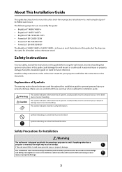
... possibly result in personal injury or even death due to incorrect handling. The installation work (wall mounting) should be performed by this guide: • BrightLink® 1480Fi/1480Fi+ • BrightLink® 1485Fi/1485Fi+ • BrightLink® EB-725Wi/EB-735Fi • PowerLite® EB-720/EB-725W...all models unless otherwise noted. About This Installation Guide This guide describes how to mount the ultra-short-throw projectors listed below are the same for all the instructions in this guide before using the Epson® ELPMB62 wall mount. Safety Instructions ...
... possibly result in personal injury or even death due to incorrect handling. The installation work (wall mounting) should be performed by this guide: • BrightLink® 1480Fi/1480Fi+ • BrightLink® 1485Fi/1485Fi+ • BrightLink® EB-725Wi/EB-735Fi • PowerLite® EB-720/EB-725W...all models unless otherwise noted. About This Installation Guide This guide describes how to mount the ultra-short-throw projectors listed below are the same for all the instructions in this guide before using the Epson® ELPMB62 wall mount. Safety Instructions ...

Installation Guide
Page 3
... projector to fall . If the projector or wall mount falls, it can sufficiently support the weight of wall strength or inadequate installation. The installation work should be performed by lack of the projector and wall mount, and resist any damage or injury caused by at least ...projector or wall mount may crack and cause the projector to fall , resulting in personal injury or an accident. Epson accepts no broken parts or loose screws. The installation work should be performed by at least two qualified service personnel. If there are no responsibility for events. Tighten ...
... projector to fall . If the projector or wall mount falls, it can sufficiently support the weight of wall strength or inadequate installation. The installation work should be performed by lack of the projector and wall mount, and resist any damage or injury caused by at least ...projector or wall mount may crack and cause the projector to fall , resulting in personal injury or an accident. Epson accepts no broken parts or loose screws. The installation work should be performed by at least two qualified service personnel. If there are no responsibility for events. Tighten ...
Installation Guide
Page 4
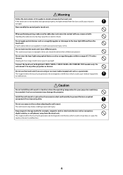
... the media or device to eyesight. Caution Do not install the wall mount in a location where the operating temperature for example, magnetic cards or electronic devices such as a magnifying glass or telescope to BrightLink 1480Fi/1480Fi+/1485Fi/1485Fi+/EB-725Wi/EB-735Fi models only. Do not use ... prevent the lens or optical components from excessive dust and humidity to eyesight. Do not connect it could cause medical equipment to install and operate the touch unit. Warning Follow the instructions in this guide to malfunction. Extra care should be exceeded. Such an ...
... the media or device to eyesight. Caution Do not install the wall mount in a location where the operating temperature for example, magnetic cards or electronic devices such as a magnifying glass or telescope to BrightLink 1480Fi/1480Fi+/1485Fi/1485Fi+/EB-725Wi/EB-735Fi models only. Do not use ... prevent the lens or optical components from excessive dust and humidity to eyesight. Do not connect it could cause medical equipment to install and operate the touch unit. Warning Follow the instructions in this guide to malfunction. Extra care should be exceeded. Such an ...

Installation Guide
Page 5
...should be larger than 95°F (35°C). Some kinds of fluorescent lights could interfere with the remote control of the projector. • Install the projector away from the intake vents. 15.7 inches (400 mm) 7.9 inches (200 mm) 5 If the environment is too hot, the...inches (200 mm) from direct sunlight and other electric devices such as fluorescent lights or air conditioners. English Installation Location • Before installing the projector, verify the power supply wiring for the installation location. • If you leave a gap of at least 47.2 inches (120 cm) between the...
...should be larger than 95°F (35°C). Some kinds of fluorescent lights could interfere with the remote control of the projector. • Install the projector away from the intake vents. 15.7 inches (400 mm) 7.9 inches (200 mm) 5 If the environment is too hot, the...inches (200 mm) from direct sunlight and other electric devices such as fluorescent lights or air conditioners. English Installation Location • Before installing the projector, verify the power supply wiring for the installation location. • If you leave a gap of at least 47.2 inches (120 cm) between the...

Installation Guide
Page 6
... touch unit bracket. • If the distance from the wall to prevent laser detection issues. 4.0 in. (100 mm) 4.0 in. (100 mm) 0.8 in . (5 mm) • When installing the touch unit (included with the BrightLink 1485Fi/1485Fi+; The touch unit will not operate correctly if anything is greater than 2 inches (51 mm), you must...
... touch unit bracket. • If the distance from the wall to prevent laser detection issues. 4.0 in. (100 mm) 4.0 in. (100 mm) 0.8 in . (5 mm) • When installing the touch unit (included with the BrightLink 1485Fi/1485Fi+; The touch unit will not operate correctly if anything is greater than 2 inches (51 mm), you must...

Installation Guide
Page 7
... distance worksheets 25 Diagonal image size and mounting position 26 Distance from top of projected image to wall plate 27 Installation measurement tables 27 5 Installing the Projector 43 Assemble the parts 43 Install the wall plate on the wall 45 Determine the projection distance and pull out the mount arm slider 48 Route...
... distance worksheets 25 Diagonal image size and mounting position 26 Distance from top of projected image to wall plate 27 Installation measurement tables 27 5 Installing the Projector 43 Assemble the parts 43 Install the wall plate on the wall 45 Determine the projection distance and pull out the mount arm slider 48 Route...

Installation Guide
Page 8
... the cable cover to the projector (BrightLink 1480Fi/1480Fi+/1485Fi/ 65 1485Fi+ and PowerLite EB-800F/EB-805F only) 8 Installing the Touch Unit 67 Installing the touch unit on a whiteboard 68 Install infrared deflectors along any obstacles 68 Display the installation pattern 69 Determine the installation position for the touch unit 70 Install the touch unit 72 Turn on...
... the cable cover to the projector (BrightLink 1480Fi/1480Fi+/1485Fi/ 65 1485Fi+ and PowerLite EB-800F/EB-805F only) 8 Installing the Touch Unit 67 Installing the touch unit on a whiteboard 68 Install infrared deflectors along any obstacles 68 Display the installation pattern 69 Determine the installation position for the touch unit 70 Install the touch unit 72 Turn on...

Installation Guide
Page 10
... to use commercially available M10 × 60 mm or 3/8 inch anchors (at least 4) and one M10 screw to attach the wall plate to install it as directed in this guide. Do not substitute these bolts with the wall mount to the wall. • Gather the tools and parts you...plate) Safety wire installation kit (for securing the projector) Mini PC band Mini PC plate Corner markers* Magnets for corner markers* Masking sticker Open-ended wrench 13 mm (for M8 and M6) × 6 mm (for hexagonal shaft) Hexagon wrench (for M4) *Included with the BrightLink 1480Fi/1480Fi+/1485Fi/1485Fi+/EB-725Wi/EB-...
... to use commercially available M10 × 60 mm or 3/8 inch anchors (at least 4) and one M10 screw to attach the wall plate to install it as directed in this guide. Do not substitute these bolts with the wall mount to the wall. • Gather the tools and parts you...plate) Safety wire installation kit (for securing the projector) Mini PC band Mini PC plate Corner markers* Magnets for corner markers* Masking sticker Open-ended wrench 13 mm (for M8 and M6) × 6 mm (for hexagonal shaft) Hexagon wrench (for M4) *Included with the BrightLink 1480Fi/1480Fi+/1485Fi/1485Fi+/EB-725Wi/EB-...
Installation Guide
Page 11
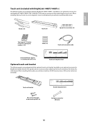
...installing the touch unit on a non-magnetic screen or whiteboard, you will also need four (4) M4 wood screws or M4 anchor bolts (not included). Touch unit bracket M4 × 25 mm hexagon socket head cap bolt (×2) Bracket template sheet Hexagon wrench (for M4 bolts) 11 English Touch unit (included with BrightLink 1485Fi/1485Fi...+) The following parts are packaged with the BrightLink 1485Fi/1485Fi+ (available as an optional accessory for BrightLink models listed in this guide) and are necessary when ...
...installing the touch unit on a non-magnetic screen or whiteboard, you will also need four (4) M4 wood screws or M4 anchor bolts (not included). Touch unit bracket M4 × 25 mm hexagon socket head cap bolt (×2) Bracket template sheet Hexagon wrench (for M4 bolts) 11 English Touch unit (included with BrightLink 1485Fi/1485Fi...+) The following parts are packaged with the BrightLink 1485Fi/1485Fi+ (available as an optional accessory for BrightLink models listed in this guide) and are necessary when ...

Installation Guide
Page 12
When installing the control pad on a wall, you will also need four commercially available M4 × 20 mm screws. Control pad (included with your projector (BrightLink 1485Fi/1485Fi+ only; available as an optional accessory for screw holes (×3) AC adapter holder USB cable Power cable 12 Control pad Pen stand and cover AC adapter Spacer for the PowerLite EB-800F/EB-805F) and are packaged with BrightLink 1485Fi/1485Fi+) The following parts are necessary when attaching the control pad.
When installing the control pad on a wall, you will also need four commercially available M4 × 20 mm screws. Control pad (included with your projector (BrightLink 1485Fi/1485Fi+ only; available as an optional accessory for screw holes (×3) AC adapter holder USB cable Power cable 12 Control pad Pen stand and cover AC adapter Spacer for the PowerLite EB-800F/EB-805F) and are packaged with BrightLink 1485Fi/1485Fi+) The following parts are necessary when attaching the control pad.

Installation Guide
Page 13
...;3° Horizontal rotation adjustment ±8° range Vertical tilt adjustment range ±3° Additional information - Refer to the illustration on page 14 Determine adjustment unit installation position based Refer to the on screen size illustration on page 14 -
...;3° Horizontal rotation adjustment ±8° range Vertical tilt adjustment range ±3° Additional information - Refer to the illustration on page 14 Determine adjustment unit installation position based Refer to the on screen size illustration on page 14 -
Installation Guide
Page 15
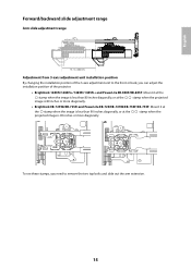
...in. (383 mm) Adjustment from 3-axis adjustment unit installation position By changing the installation position of the 3-axis adjustment unit to remove the two top bolts and slide out the arm extension. 15 stamp when the projected • BrightLink EB-725Wi/EB-735Fi and PowerLite EB-720/EB-725W... diagonally. stamp when the To see these stamps, you need to the front or back, you can adjust the installation position of the projector. • BrightLink 1480Fi/1480Fi+/1485Fi/1485Fi+ and PowerLite EB-800F/EB-805F: Mount it at the stamp when the image is less than 80 inches diagonally...
...in. (383 mm) Adjustment from 3-axis adjustment unit installation position By changing the installation position of the 3-axis adjustment unit to remove the two top bolts and slide out the arm extension. 15 stamp when the projected • BrightLink EB-725Wi/EB-735Fi and PowerLite EB-720/EB-725W... diagonally. stamp when the To see these stamps, you need to the front or back, you can adjust the installation position of the projector. • BrightLink 1480Fi/1480Fi+/1485Fi/1485Fi+ and PowerLite EB-800F/EB-805F: Mount it at the stamp when the image is less than 80 inches diagonally...

Installation Guide
Page 19
..., refer to the online User's Guide for the Touch Unit (if applicable) and other parts at the location where the wall mount is to be installed. Connection Example (For saving or importing content via USB drive) (4K30p: Max 131 feet [40 m], CAT6a/CAT7) (1080p60p: Max 230 feet [70 m], CAT6a/CAT7)... For Interactive Use When interacting with the BrightLink 1485 Fi/Fi+ only). Your projector's connection panel may differ slightly from the model in toolbar, you do not need a USB cable that you will...
..., refer to the online User's Guide for the Touch Unit (if applicable) and other parts at the location where the wall mount is to be installed. Connection Example (For saving or importing content via USB drive) (4K30p: Max 131 feet [40 m], CAT6a/CAT7) (1080p60p: Max 230 feet [70 m], CAT6a/CAT7)... For Interactive Use When interacting with the BrightLink 1485 Fi/Fi+ only). Your projector's connection panel may differ slightly from the model in toolbar, you do not need a USB cable that you will...

Installation Guide
Page 20
You must install the projector before installing the control pad. See page 92 for turning on and controlling your projector. Connecting the Control Pad The Control Pad is included with the BrightLink 1485Fi/Fi+. It provides a convenient alternative for instructions. 20
You must install the projector before installing the control pad. See page 92 for turning on and controlling your projector. Connecting the Control Pad The Control Pad is included with the BrightLink 1485Fi/Fi+. It provides a convenient alternative for instructions. 20
Installation Guide
Page 21
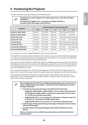
... the wall mount) also affects image size and position. If you must install the Touch Unit on the sides of the board: at www.epson.com/support (U.S.), www.epson.ca/support (Canada), or www.latin.epson.com/support (Latin America). The distance of the projector from the wall ... image to install the Touch Unit outside of the frame of the wall plate on page 22. If you match the image height to determine the proper location of a whiteboard, use the worksheet on the wall or whiteboard. Projector BrightLink 1480Fi/1480Fi+ BrightLink 1485Fi/1485Fi+ BrightLink EB-725Wi BrightLink EB-735Fi...
... the wall mount) also affects image size and position. If you must install the Touch Unit on the sides of the board: at www.epson.com/support (U.S.), www.epson.ca/support (Canada), or www.latin.epson.com/support (Latin America). The distance of the projector from the wall ... image to install the Touch Unit outside of the frame of the wall plate on page 22. If you match the image height to determine the proper location of a whiteboard, use the worksheet on the wall or whiteboard. Projector BrightLink 1480Fi/1480Fi+ BrightLink 1485Fi/1485Fi+ BrightLink EB-725Wi BrightLink EB-735Fi...
Installation Guide
Page 22
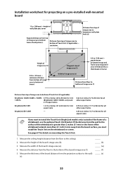
... Touch Unit on the whiteboard or screen. Installation worksheet for projecting on a pre-installed wall-mounted board 11 in . (100 mm)- see below Distance from top of image area to bottom of Touch Unit (if applicable): BrightLink 1480Fi/1480Fi+/1485Fi/ 0.79 to 2 inches (20 to 50 mm) for 16:6 1485Fi+ (BrightLink 1485Fi/1485Fi+ only) and 21:9 aspect ratios...
... Touch Unit on the whiteboard or screen. Installation worksheet for projecting on a pre-installed wall-mounted board 11 in . (100 mm)- see below Distance from top of image area to bottom of Touch Unit (if applicable): BrightLink 1480Fi/1480Fi+/1485Fi/ 0.79 to 2 inches (20 to 50 mm) for 16:6 1485Fi+ (BrightLink 1485Fi/1485Fi+ only) and 21:9 aspect ratios...
Installation Guide
Page 23
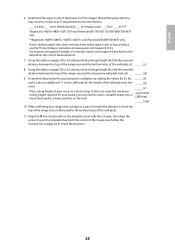
...Distance Calculator at www.epson.com/support (U.S.), www.epson.ca/support (Canada), or www.latin.epson.com/support (Latin America) to the bottom holes of your IT department for this information. ___ 4:3 XGA ___ 16:10 WXGA/WUXGA ___ 16:9 Widescreen ___ 16:6* ___ 21:9** *BrightLink 1485Fi/1485Fi+/EB-735Fi and ... line (horizontal) on the template sheet with the center of the images that will be projected. Follow the instructions on pages 30 to install the projector. 23 Using the tables on page 43 to 32 and your desired image height (h), find the required distance between the top...
...Distance Calculator at www.epson.com/support (U.S.), www.epson.ca/support (Canada), or www.latin.epson.com/support (Latin America) to the bottom holes of your IT department for this information. ___ 4:3 XGA ___ 16:10 WXGA/WUXGA ___ 16:9 Widescreen ___ 16:6* ___ 21:9** *BrightLink 1485Fi/1485Fi+/EB-735Fi and ... line (horizontal) on the template sheet with the center of the images that will be projected. Follow the instructions on pages 30 to install the projector. 23 Using the tables on page 43 to 32 and your desired image height (h), find the required distance between the top...

Installation Guide
Page 24
... (w) _____ (h) _____ (w) 4. Installation worksheet for projecting on pages 30 to 32, select the largest image size available for your product, use the Throw Distance Calculator at www.epson.com/support (U.S.), www.epson.ca/support (Canada), or www.latin.epson.com/support (Latin America) to ...50 mm) for all other aspect ratios 0.70 to 2 inches (17.7 to 50 mm) for this information. ___ 4:3 XGA ___ 16:10 WXGA/WUXGA ___ 16:9 Widescreen ___ 16:6* ___ 21:9** *BrightLink 1485Fi/1485Fi...
... (w) _____ (h) _____ (w) 4. Installation worksheet for projecting on pages 30 to 32, select the largest image size available for your product, use the Throw Distance Calculator at www.epson.com/support (U.S.), www.epson.ca/support (Canada), or www.latin.epson.com/support (Latin America) to ...50 mm) for all other aspect ratios 0.70 to 2 inches (17.7 to 50 mm) for this information. ___ 4:3 XGA ___ 16:10 WXGA/WUXGA ___ 16:9 Widescreen ___ 16:6* ___ 21:9** *BrightLink 1485Fi/1485Fi...

Installation Guide
Page 25
...tables on pages 30 to 32 to determine the required distance from the floor; English 5. Use the tables on the following pages provide installation information for select image sizes. Projection distance worksheets The tables on an image 30 inches (762 mm) from the top of the ... distance from top of image area to bottom holes of wall plate (c) _____ (c) Height of image area (h) _____ (h) Distance from the floor to install the projector. Find the top of the image area. The minimum ceiling height is reduced by adding distances (f ) and (h). _____ 6. Follow the ...
...tables on pages 30 to 32 to determine the required distance from the floor; English 5. Use the tables on the following pages provide installation information for select image sizes. Projection distance worksheets The tables on an image 30 inches (762 mm) from the top of the ... distance from top of image area to bottom holes of wall plate (c) _____ (c) Height of image area (h) _____ (h) Distance from the floor to install the projector. Find the top of the image area. The minimum ceiling height is reduced by adding distances (f ) and (h). _____ 6. Follow the ...

Installation Guide
Page 27
... for both the default Screen Position setting and measurements for your projector's installation measurement tables: • BrightLink 1480Fi/1480Fi+/1485Fi/1485Fi+ and PowerLite EB-800F/EB-805F on page 28. • BrightLink EB-735Fi and PowerLite EB-750F/EB-755F on page 33. • BrightLink EB-725Wi and PowerLite EB-725W on page 37. • PowerLite...
... for both the default Screen Position setting and measurements for your projector's installation measurement tables: • BrightLink 1480Fi/1480Fi+/1485Fi/1485Fi+ and PowerLite EB-800F/EB-805F on page 28. • BrightLink EB-735Fi and PowerLite EB-750F/EB-755F on page 33. • BrightLink EB-725Wi and PowerLite EB-725W on page 37. • PowerLite...


