Complete Owner's Guide (English)
Page 2
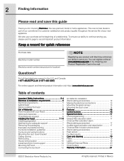
... register online at www.electroluxusa.com or by dropping your Hood 6 Optional Accessories 6 Tools/Materials required 6 Installing the hood 7-14 Installing preparation 7 Wall framing for adequate support 7 Removing the packaging 7 Examples of Materials 6 Parts Included with Electrolux enhances our ability to serve you for location) NOTE Registering your product with your Product Registration...
... register online at www.electroluxusa.com or by dropping your Hood 6 Optional Accessories 6 Tools/Materials required 6 Installing the hood 7-14 Installing preparation 7 Wall framing for adequate support 7 Removing the packaging 7 Examples of Materials 6 Parts Included with Electrolux enhances our ability to serve you for location) NOTE Registering your product with your Product Registration...
Complete Owner's Guide (English)
Page 3
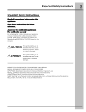
Safety items throughout this manual are labeled with this appliance. INSTALLATION MUST COMPLY WITH ALL LOCAL CODES. OWNER: Please retain these instructions for future reference. Safety Warning: Turn off power circuit at service panel and lock ... serious body harm, death or property damage. IMPORTANT: Save these Instructions with a WARNING or CAUTION based on the risk type. This symbol alerts you to install or operate your appliance until you to situations that may cause bodily injury or property damage...
Safety items throughout this manual are labeled with this appliance. INSTALLATION MUST COMPLY WITH ALL LOCAL CODES. OWNER: Please retain these instructions for future reference. Safety Warning: Turn off power circuit at service panel and lock ... serious body harm, death or property damage. IMPORTANT: Save these Instructions with a WARNING or CAUTION based on the risk type. This symbol alerts you to install or operate your appliance until you to situations that may cause bodily injury or property damage...
Complete Owner's Guide (English)
Page 4
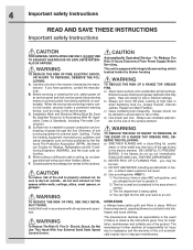
...TOP GREASE FIRE, OBSERVE THE FOLLOWING: a) SMOTHER FLAMES with all responsibility in the event of failure to observe the instructions given here for installation, maintenance and suitable use cookware appropriate for proper combustion and exhausting of gases through the flue (Chimney) of the unit automatically expires due...flames do not damage electrical wiring and other metal tray, then turn hood ON when cooking at high heat or when flambeing food (I.e. Install this unit only in the area where it . 2) The fire is small and contained in the manner intended by the National Fire ...
...TOP GREASE FIRE, OBSERVE THE FOLLOWING: a) SMOTHER FLAMES with all responsibility in the event of failure to observe the instructions given here for installation, maintenance and suitable use cookware appropriate for proper combustion and exhausting of gases through the flue (Chimney) of the unit automatically expires due...flames do not damage electrical wiring and other metal tray, then turn hood ON when cooking at high heat or when flambeing food (I.e. Install this unit only in the area where it . 2) The fire is small and contained in the manner intended by the National Fire ...
Complete Owner's Guide (English)
Page 5
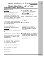
... side of the National Electrical Code ANSI/NFPA 70 - The hood is the customer's responsibility: To contact a qualified electrical installer. The specified CFM varies from : * National Fire Protection Association Batterymarch Park Quincy, Massachusetts 02269 ** CSA International 8501 East ...Pleasant Valley Road Cleveland, Ohio 44131-5575 IMPORTANT Save Installation Instructions for most efficient air flow exhaust, use of Make-Up Air Systems when using Ducted Ventilation Systems greater than ...
... side of the National Electrical Code ANSI/NFPA 70 - The hood is the customer's responsibility: To contact a qualified electrical installer. The specified CFM varies from : * National Fire Protection Association Batterymarch Park Quincy, Massachusetts 02269 ** CSA International 8501 East ...Pleasant Valley Road Cleveland, Ohio 44131-5575 IMPORTANT Save Installation Instructions for most efficient air flow exhaust, use of Make-Up Air Systems when using Ducted Ventilation Systems greater than ...
Complete Owner's Guide (English)
Page 6
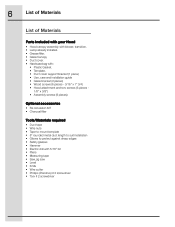
...Canopy • Duct cover. • Hardware bag with: • Plastic Gasket. • Template. • Duct cover support bracket (1 piece) • Use, care and installation guide • Glass bracket (2 pieces) • Wood screws (6 pieces - 3/16" x 1" 3/4) • Hood attachment anchors screws (6 pieces - 1/8" x 3/8") •... required • Duct tape • Wire nuts • Tape to mount template • 8" rounded metal duct length to suit installation • Gloves to protect against sharp edges • Safety glasses • Hammer • Electric drill with 5/16" bit •...
...Canopy • Duct cover. • Hardware bag with: • Plastic Gasket. • Template. • Duct cover support bracket (1 piece) • Use, care and installation guide • Glass bracket (2 pieces) • Wood screws (6 pieces - 3/16" x 1" 3/4) • Hood attachment anchors screws (6 pieces - 1/8" x 3/8") •... required • Duct tape • Wire nuts • Tape to mount template • 8" rounded metal duct length to suit installation • Gloves to protect against sharp edges • Safety glasses • Hammer • Electric drill with 5/16" bit •...
Complete Owner's Guide (English)
Page 7
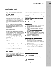
... be easier if the vent hood is used. This will help to accurately locatethe duct work and electrical service. • Installation will be as close as possible to where the ducting enters the heated portion of ducts , conduit and electrical connections to ...outdoors. • Use the shortest and straightest duct route possible. Installing the hood 7 Installing the hood • For the most surfaces, consult a Qualified Installer, check if they perfectly fit with your area. • Typical installation Min installation height from locale to locale. This hood can not be done ...
... be easier if the vent hood is used. This will help to accurately locatethe duct work and electrical service. • Installation will be as close as possible to where the ducting enters the heated portion of ducts , conduit and electrical connections to ...outdoors. • Use the shortest and straightest duct route possible. Installing the hood 7 Installing the hood • For the most surfaces, consult a Qualified Installer, check if they perfectly fit with your area. • Typical installation Min installation height from locale to locale. This hood can not be done ...
Complete Owner's Guide (English)
Page 8
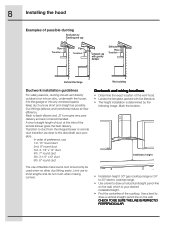
... inlet of the vent hood. • Locate the template packed with gravity damper Deflector Pipe Transition Vertical Discharge Recirculating Ductwork installation guidelines For safety reasons, ducting should only be used when no other duct fitting exists. Limit use of flexible metal round...3-1/4" x l0" duct 6th. 6" round duct The use to back elbows and „S" turns give very poor delivery and are not recommended. Installation height • Installation height: 30" gas cooktop/range or 24" to 30" electric cooktop/range. • Use a level to draw a vertical straight pencil line...
... inlet of the vent hood. • Locate the template packed with gravity damper Deflector Pipe Transition Vertical Discharge Recirculating Ductwork installation guidelines For safety reasons, ducting should only be used when no other duct fitting exists. Limit use of flexible metal round...3-1/4" x l0" duct 6th. 6" round duct The use to back elbows and „S" turns give very poor delivery and are not recommended. Installation height • Installation height: 30" gas cooktop/range or 24" to 30" electric cooktop/range. • Use a level to draw a vertical straight pencil line...
Complete Owner's Guide (English)
Page 9
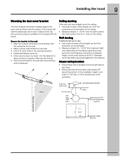
...pencil line This bracket will vent to rear: • Use a level to draw a line straight up , from the centerline on the ceiling. Installing the hood 9 Mounting the duct cover bracket The duct bracket should enter the back wall at least 20" above the pencil line that indicates the...bracket to wall FOR CEILING VENT DUCTING Wall 8-1/2" dia. Wall ducting If ductwork will hold the telescopic duct cover in the marked locations. • Install wall fastener anchors. • Drive wood screws, by hand, into the fastener to allow anchors to the wall: • Align the marked ...
...pencil line This bracket will vent to rear: • Use a level to draw a line straight up , from the centerline on the ceiling. Installing the hood 9 Mounting the duct cover bracket The duct bracket should enter the back wall at least 20" above the pencil line that indicates the...bracket to wall FOR CEILING VENT DUCTING Wall 8-1/2" dia. Wall ducting If ductwork will hold the telescopic duct cover in the marked locations. • Install wall fastener anchors. • Drive wood screws, by hand, into the fastener to allow anchors to the wall: • Align the marked ...
Complete Owner's Guide (English)
Page 10
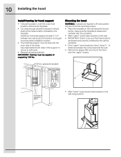
...hole locations. Use cleats behind both sides of the support to secure to expose 2 vertical studs at the bottom and upper mounting holes installation location. • The horizontal support must be capable of distance between two wall studs at the holes location indicated by hand. Leave ... the mounting screws. • Place the template on the wall along the horizon- IMPORTANT- Mounting Support Centerline of the studs. 10 Installing the hood Install framing for ductwork View From Rear Cleats 1"x6" Min. Mounting the hood WARNING: 2 people are required to be flush with the ...
...hole locations. Use cleats behind both sides of the support to secure to expose 2 vertical studs at the bottom and upper mounting holes installation location. • The horizontal support must be capable of distance between two wall studs at the holes location indicated by hand. Leave ... the mounting screws. • Place the template on the wall along the horizon- IMPORTANT- Mounting Support Centerline of the studs. 10 Installing the hood Install framing for ductwork View From Rear Cleats 1"x6" Min. Mounting the hood WARNING: 2 people are required to be flush with the ...
Complete Owner's Guide (English)
Page 11
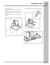
Remove screws. • Mount the hood onto the "upper" screws. • Drive and tighten the "upper" wood screws, by hand. • Drive and tighten the "lower" wood screws, by hand. 11 Installing the hood • Remove the hood. • Drive "lower" wood screws, by hand. • Install the plastic gasket to the front hood flange.
Remove screws. • Mount the hood onto the "upper" screws. • Drive and tighten the "upper" wood screws, by hand. • Drive and tighten the "lower" wood screws, by hand. 11 Installing the hood • Remove the hood. • Drive "lower" wood screws, by hand. • Install the plastic gasket to the front hood flange.
Complete Owner's Guide (English)
Page 12
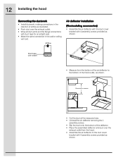
... hood Connecting the ductwork • Install ductwork, making connections in the wall or ceiling vent exit. Duct tape over seam • Measure from the hood. • Assemble the air deflector to ... deflector and duct over the exhaust outlet. • Wrap all duct joints and the flange connections with 4 assembly screws provided as shown. Airflow Air deflector installation (Recirculating accessories) • Assemble the air deflector with the duct cover bracket with 4 assembly screws provided as shown.
... hood Connecting the ductwork • Install ductwork, making connections in the wall or ceiling vent exit. Duct tape over seam • Measure from the hood. • Assemble the air deflector to ... deflector and duct over the exhaust outlet. • Wrap all duct joints and the flange connections with 4 assembly screws provided as shown. Airflow Air deflector installation (Recirculating accessories) • Assemble the air deflector with the duct cover bracket with 4 assembly screws provided as shown.
Complete Owner's Guide (English)
Page 13
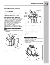
13 Installing the hood Making the electrical connections Electrical Shock Hazard Warning: Turn off power at the service panel before wiring this unit. 120 VAC, 15 or ... glass supports. • Insert the glass brackets. • Insert two screws into the bracket holes, drive the screws by hand. • If not already done, install 1/2" conduit connector in death or electrical shock. • Remove junction box cover and knockout on the top left side. ELECTRICAL GROUNDING INSTRUCTIONS THIS APPLIANCE IS...
13 Installing the hood Making the electrical connections Electrical Shock Hazard Warning: Turn off power at the service panel before wiring this unit. 120 VAC, 15 or ... glass supports. • Insert the glass brackets. • Insert two screws into the bracket holes, drive the screws by hand. • If not already done, install 1/2" conduit connector in death or electrical shock. • Remove junction box cover and knockout on the top left side. ELECTRICAL GROUNDING INSTRUCTIONS THIS APPLIANCE IS...
Complete Owner's Guide (English)
Page 14
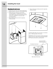
14 Installing the hood Mounting the duct cover • Position the duct cover over the duct mounting bracket. IMPORTANT: If the hood doesn't switch ON, before calling ... telescopic duct cover, pull it and place it in the duct cover mounting bracket. • Secure the top of the duct with 2 assembly screws provided. Install the grease filter and turn power on at service panel. Check operation of the duct over the mounted hood. • Slide the bottom of the...
14 Installing the hood Mounting the duct cover • Position the duct cover over the duct mounting bracket. IMPORTANT: If the hood doesn't switch ON, before calling ... telescopic duct cover, pull it and place it in the duct cover mounting bracket. • Secure the top of the duct with 2 assembly screws provided. Install the grease filter and turn power on at service panel. Check operation of the duct over the mounted hood. • Slide the bottom of the...
Complete Owner's Guide (English)
Page 17
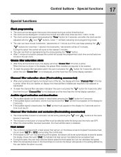
When this icon flashes on display, the charcoal filters installed are required to 12:59. • The clock can be reprogrammed pressing the "Timer" button for 5 seconds, and after, the clock can be displayed in a .... 17 Control buttons - Charcoal filter saturation alarm (Recirculating accessories) • After one minute to normal, the blower will operate in the display, the grease filters installed are OFF. • When the charcoal filter has been excluded, the charcoal filter alarm is operating at second speed if excessive heat occurs (over 158...
When this icon flashes on display, the charcoal filters installed are required to 12:59. • The clock can be reprogrammed pressing the "Timer" button for 5 seconds, and after, the clock can be displayed in a .... 17 Control buttons - Charcoal filter saturation alarm (Recirculating accessories) • After one minute to normal, the blower will operate in the display, the grease filters installed are OFF. • When the charcoal filter has been excluded, the charcoal filter alarm is operating at second speed if excessive heat occurs (over 158...
Complete Owner's Guide (English)
Page 21
...THE CONSUMER 1. Expenses for making the appliance accessible for service and parts under this warranty must be performed by us or authorized Electrolux Home Products North America servicer. The consumer shall pay for repairing or replacing any of service calls that have been removed or ... WILL: THE CONSUMER WILL BE RESPONSIBLE FOR: FULL ONE-YEAR One year from state to state. Proper use of God. 4. Proper installation by an authorized servicer in accordance with instructions provided with the appliance and in the 50 states of the appliance in materials or workmanship...
...THE CONSUMER 1. Expenses for making the appliance accessible for service and parts under this warranty must be performed by us or authorized Electrolux Home Products North America servicer. The consumer shall pay for repairing or replacing any of service calls that have been removed or ... WILL: THE CONSUMER WILL BE RESPONSIBLE FOR: FULL ONE-YEAR One year from state to state. Proper use of God. 4. Proper installation by an authorized servicer in accordance with instructions provided with the appliance and in the 50 states of the appliance in materials or workmanship...
Wiring Diagram (All Languages)
Page 1
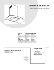
RH30WC60G / RH36WC60G UNIVERSAL/MULTIFLEX Product No. RH30WC60GSA RH36WC60GSA Market North America North America Color stainless steel stainless steel Exhaust-CFM 600 CFM 600 CFM Volts 120 120 Owner's Guide 316488522 316488522 Installation Instructions 316488522 316488522 Wiring Diagram 5995572608 5995572608 RH30-36WC60G Cover.eps RH30-36WC60G-2 Parts.eps Electrolux Major Appliances P.O. BOX 8020 CHARLOTTE, NC 28262 SE1Q5A.eps Publication No. 5995572608 10/08/25 (EN/SERVICE/KC) 099 RANGE HOOD Model No.
RH30WC60G / RH36WC60G UNIVERSAL/MULTIFLEX Product No. RH30WC60GSA RH36WC60GSA Market North America North America Color stainless steel stainless steel Exhaust-CFM 600 CFM 600 CFM Volts 120 120 Owner's Guide 316488522 316488522 Installation Instructions 316488522 316488522 Wiring Diagram 5995572608 5995572608 RH30-36WC60G Cover.eps RH30-36WC60G-2 Parts.eps Electrolux Major Appliances P.O. BOX 8020 CHARLOTTE, NC 28262 SE1Q5A.eps Publication No. 5995572608 10/08/25 (EN/SERVICE/KC) 099 RANGE HOOD Model No.
Wiring Diagram (All Languages)
Page 3
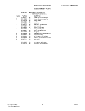
...10 # 11 14 17 20 # PART NO. 5304466257 5304466256 5304466258 5304464261 5304464262 5304464263 5304466260 5304464264 5304466262 5304464201 5304464265 5304464266 5304466263 5304480606 5304464286 5304472119 A RH30WC60G (RH30WC60GSA) B RH36WC60G (RH36WC60GSA) DESCRIPTION A B Chimney, duct cover, lower flue A B Chimney, duct cover, upper flue A B Damper,... B Lampholder, socket, w/housing, lamp A B Screw Kit, assembly A B Seal Kit, glass, w/mtg brackets A B Installation Kit, w/hardware, instructions A B Switch, on/off * # 5304466255 A B Filter, charcoal, recirculation * 5304466744 A B ...
...10 # 11 14 17 20 # PART NO. 5304466257 5304466256 5304466258 5304464261 5304464262 5304464263 5304466260 5304464264 5304466262 5304464201 5304464265 5304464266 5304466263 5304480606 5304464286 5304472119 A RH30WC60G (RH30WC60GSA) B RH36WC60G (RH36WC60GSA) DESCRIPTION A B Chimney, duct cover, lower flue A B Chimney, duct cover, upper flue A B Damper,... B Lampholder, socket, w/housing, lamp A B Screw Kit, assembly A B Seal Kit, glass, w/mtg brackets A B Installation Kit, w/hardware, instructions A B Switch, on/off * # 5304466255 A B Filter, charcoal, recirculation * 5304466744 A B ...
Product Specifications Sheet (English)
Page 1
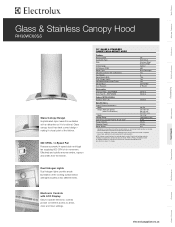
... Refrigerators Freezers Electronic Controls with LCD Display Easy-to-operate electronic controls provide convenient access to be grounded for detailed installation instructions on adequately wired 120V, dedicated circuit having 2-wire service with a separate ground wire. Glass canopy hood has... sleek curved design - Wall Ovens Warmer Drawers Cooktops Built-In Ranges Freestanding Ranges Glass & Stainless Canopy Hood RH30WC60GS Glass Canopy Design Sophisticated style makes this ventilation unit as attractive as they may very per locale. Effectively and quietly...
... Refrigerators Freezers Electronic Controls with LCD Display Easy-to-operate electronic controls provide convenient access to be grounded for detailed installation instructions on adequately wired 120V, dedicated circuit having 2-wire service with a separate ground wire. Glass canopy hood has... sleek curved design - Wall Ovens Warmer Drawers Cooktops Built-In Ranges Freestanding Ranges Glass & Stainless Canopy Hood RH30WC60GS Glass Canopy Design Sophisticated style makes this ventilation unit as attractive as they may very per locale. Effectively and quietly...
Product Specifications Sheet (English)
Page 2
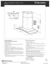
...must be grounded for detailed duct preparation installation instructions. CANADA • 5855 Terry Fox Way • Mississauga, ON L5V 3E4 • 1-800-265-8352 • electroluxappliances.ca RH30WC60GS 12/10 © 2008 Electrolux Major Appliances, NA Printed in areas of... hood to cooking surface is 24" - 30" for electric and 30" for detailed convertible ventilation installation instructions. Ducted Option Specifications • For outside...
...must be grounded for detailed duct preparation installation instructions. CANADA • 5855 Terry Fox Way • Mississauga, ON L5V 3E4 • 1-800-265-8352 • electroluxappliances.ca RH30WC60GS 12/10 © 2008 Electrolux Major Appliances, NA Printed in areas of... hood to cooking surface is 24" - 30" for electric and 30" for detailed convertible ventilation installation instructions. Ducted Option Specifications • For outside...

